Wrist-carried camera and watch-type information equipment

Inactive Publication Date: 2005-03-29
FUJIFILM CORP
View PDF14 Cites 22 Cited by
  • Summary
  • Abstract
  • Description
  • Claims
  • Application Information

AI Technical Summary

Benefits of technology

According to the present invention, the mode of the equipment is displayed on the rotatable mode display member, and the hand of the wa

Problems solved by technology

In the field of electronic cameras such as a digital camera, a great deal of effort was put into the miniaturization of the cameras.
It

Method used


Image

  • Wrist-carried camera and watch-type information equipment
  • Wrist-carried camera and watch-type information equipment
  • Wrist-carried camera and watch-type information equipment

Examples


second embodiment

The hands of the watch are not restricted to the existing mechanical structures, but they may be embodied by displaying on a display unit such as an onscreen display. the hands of the watch are embodied by the display on the display unit.

A description will now be given of the second embodiment of the present invention.

FIG. 8 is a block diagram showing the electronic camera according to the second embodiment of the present invention. Parts similar to those described with reference to FIG. 6 are denoted by the same reference numerals, and they will not be described. The electronic camera of the second embodiment is provided with a display switching circuit 70 and a display unit 72 instead of the display switching circuit 54 and the hand driving unit 56 in FIG. 6.

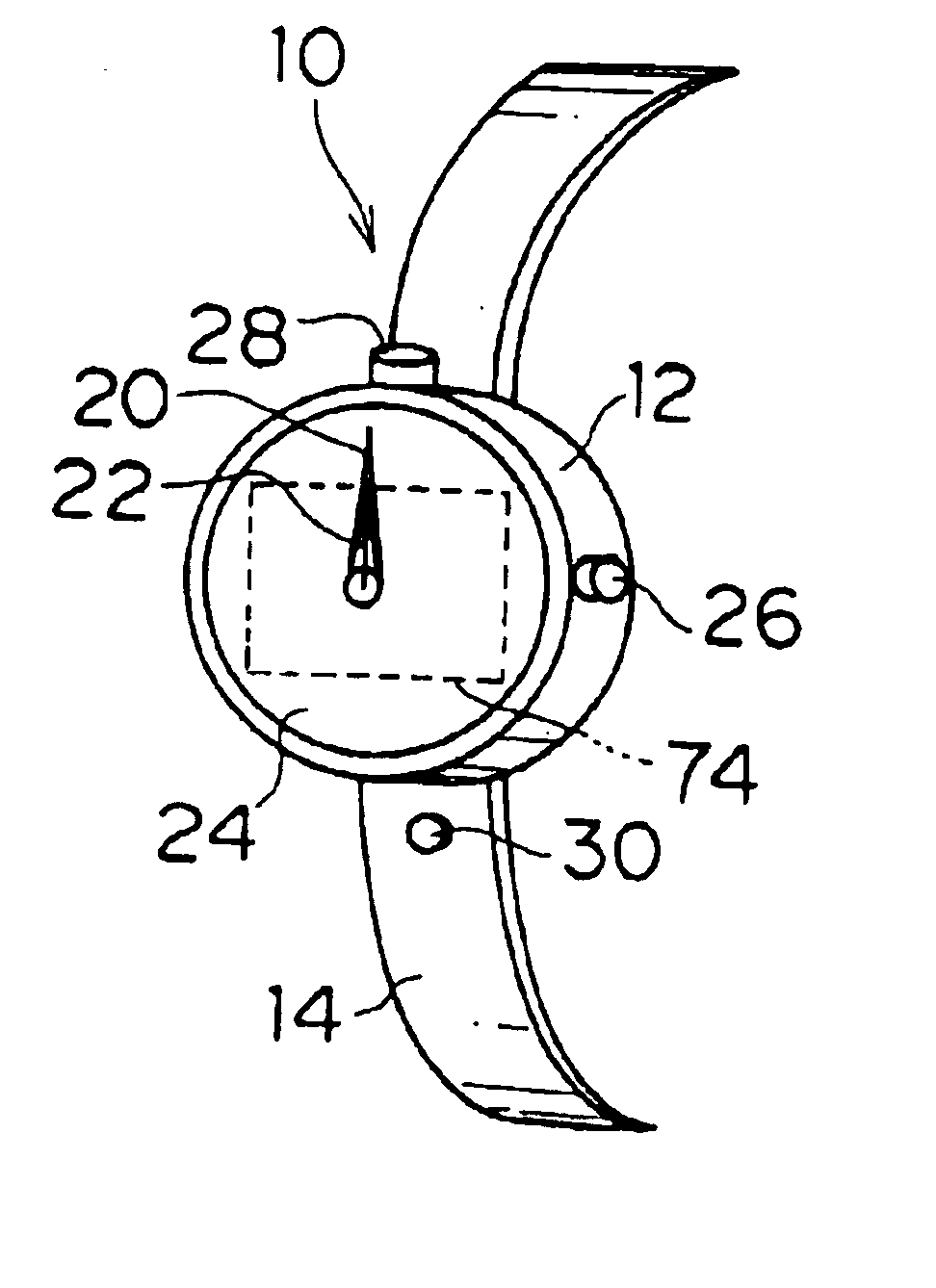
The display unit 72 such as a liquid crystal display is built in the body 12 in FIG. 1. More specifically, a display screen of the display unit 72 is arranged at a part corresponding to the display part 24 of the body 12. The...

third embodiment

A description will now be given of the present invention.

FIG. 10 shows an embodiment in which the watch-type information equipment according to the present invention is applied to the wrist-carried electronic camera. Parts similar to those described with reference to FIG. 1 are denoted by the same reference numerals, and they will not be described here. The hands of the watch may be mechanical as is the case with the first embodiment, or the display unit may be used to display the images of hands of the watch as is the second embodiment.

The taking lens (not illustrated in FIG. 10) of an electronic camera 80 in FIG. 10 is incorporated in the body 12, and does not project from the body 12. The taking lens is arranged in the direction of the twelve o'clock as is the case with in FIG. 1.

A bezel 82 is arranged to surround the display part 24, and is rotatably attached to the top of the body 12. Marks 83, 84 and 85 indicating the operation modes of the camera are formed on the bezel 82, a...


PUM


Abstract

In a wrist-carried camera having a watch function, a body including a taking lens is provided in such a manner as to freely rotate with respect to a band part through a rotation mechanism, and a release switch is provided at the unrotated band part. Setting a camera mode stops the hands of the watch in the direction of a taking lens so as to display an image-capturing direction. A rotary bezel is arranged around a display part, and marks indicating modes of the camera are formed on the bezel. A hand of the watch is also used as an indicator for pointing the mode display mark in the bezel. Setting the mark in the bezel to the indicator switches and displays the operation modes.

Description

BACKGROUND OF THE INVENTION1. Field of the InventionThe present invention relates generally to a wrist-carried camera and watch-type information equipment, and more particularly to a camera shaped to be worn about the wrist of an operator like a wristwatch, a portable information terminal and other portable small information equipment.2. Description of Related ArtIn the field of electronic cameras such as a digital camera, a great deal of effort was put into the miniaturization of the cameras. Japanese Patent Provisional Publication Nos. 5-209973, 8-278382, 10-108152, etc. disclose a variety of wrist-carried cameras. In the conventional wrist-carried camera, however, the position of the taking lens and the direction of an optical axis of the taking lens are fixed. Accordingly, the operator has to put the wrist with the worn wristwatch-type camera in front of the body to use the functions of the camera, and the operator has to move the body or the wrist to turn the taking lens toward...

Claims


Application Information

Patent Timeline
IPC IPC(8): G04B47/00G04C19/00H04N5/225G03B17/02G03B17/56G04C3/00G04G21/00
CPCG04B47/00H04N5/2252H04N5/2251G04G21/00H04N23/50H04N23/51H04N23/633
Inventor YAMAZAKI, AKIHISASAGAE, KOJI
Owner FUJIFILM CORP
Why Eureka
Try Eureka