Managing channels with different wavelengths in optical networks

a technology of optical networks and channels, applied in the field of optical networks, can solve problems such as confli

Inactive Publication Date: 2005-03-29
INTEL CORP
View PDF12 Cites 34 Cited by
  • Summary
  • Abstract
  • Description
  • Claims
  • Application Information

AI Technical Summary

Problems solved by technology

As a result, conflicts may arise where several channels of the same wavelength are delivered to the same network node and must be sent along the same fiber.

Method used


Image

  • Managing channels with different wavelengths in optical networks
  • Managing channels with different wavelengths in optical networks
  • Managing channels with different wavelengths in optical networks

Examples


Embodiment Construction

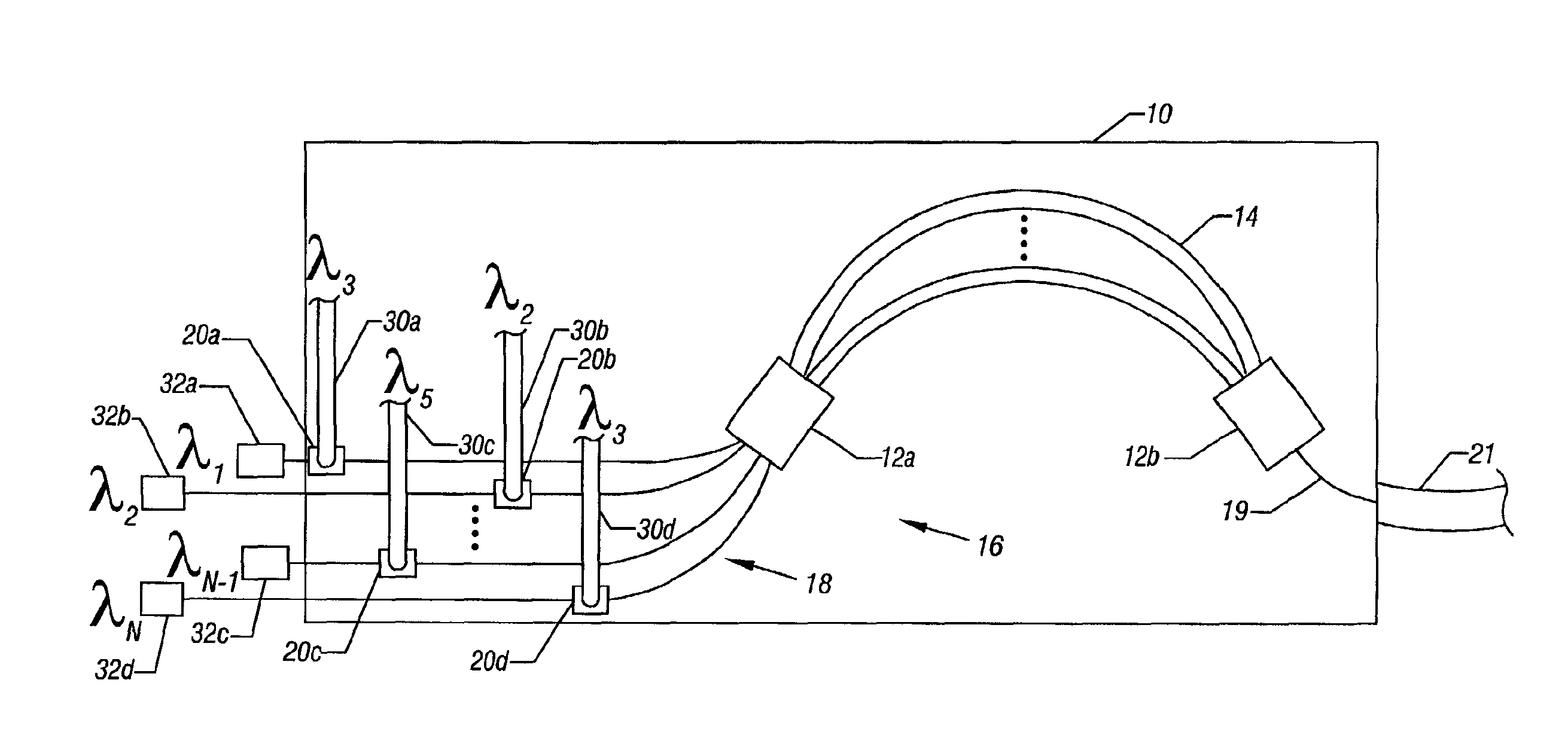
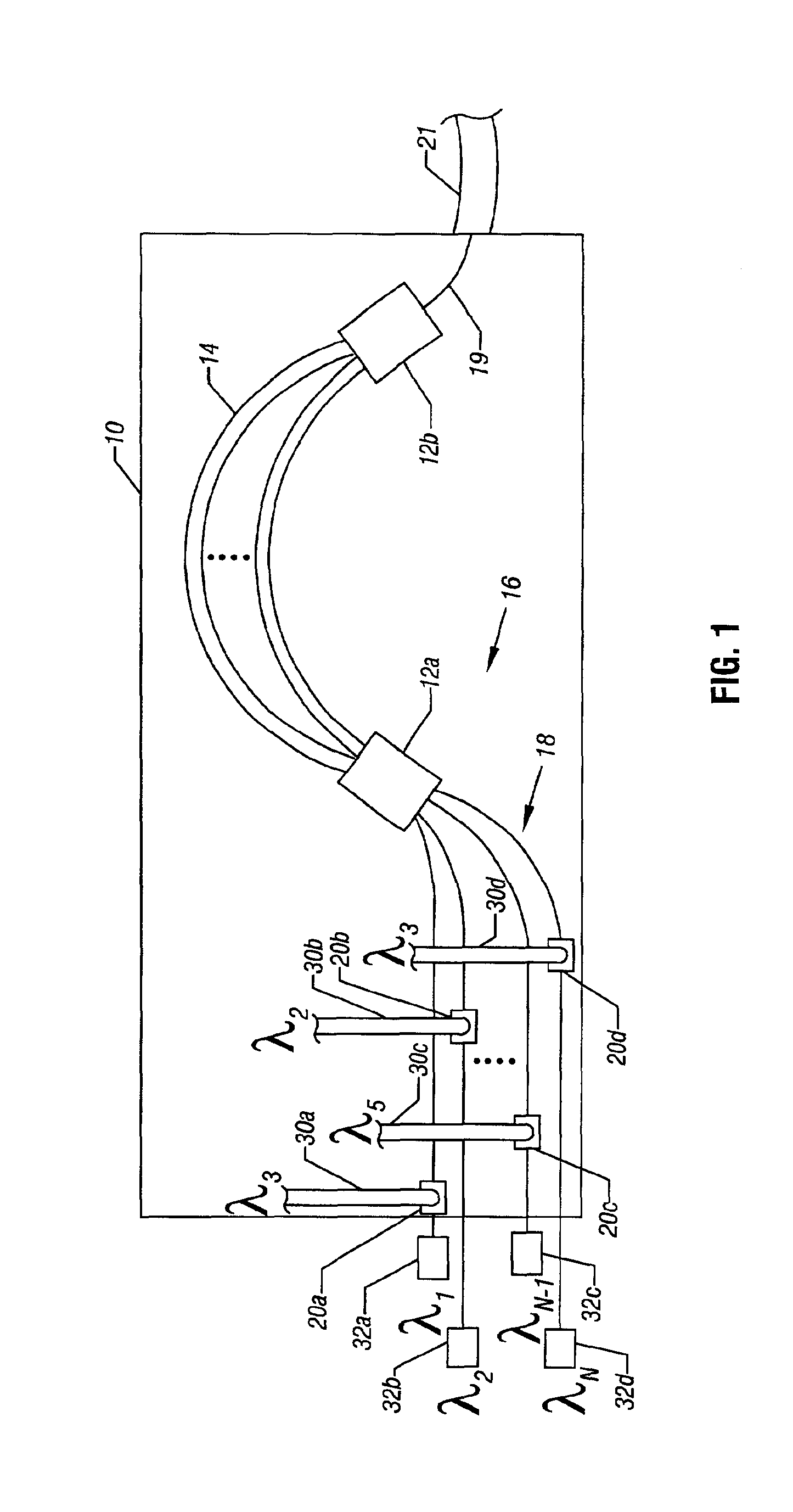
An arrayed waveguide grating (AWG) 10, sometimes also called a waveguide grating router (WGR) or a phasar, may be formed as an integrated optical circuit. The AWG 10 may include a plurality of input waveguides 18 that leads to a star coupler 12a, an array of waveguides 14 between the star coupler 12a and the star coupler 12b, and an output waveguide 19 coupled to the coupler 12b. The length of each arrayed waveguide 14 in the array of waveguides 14 may be distinguished from its adjacent waveguide by a length difference (ΔL).

A channel of certain wavelength enters the AWG in one of the input waveguides 18. The input coupler 12a splits the light in the channel among the arrayed waveguides 14. Each portion of the input light traveling through an arrayed waveguide 14 includes any wavelength that has entered the AWG 10 in any of the input channels 18. Each wavelength then acquires an individual phase shift. In addition, each wavelength for each channel receives phase shifts in the input a...


PUM


Abstract

An arrayed waveguide grating may include a plurality of waveguides, each associated with a different channel in a wavelength division multiplexed system. Each incoming signal channel in a node of a wavelength division multiplexed network may be of an arbitrary wavelength and is provided to one of the wavelength converters attached on the arrayed waveguide grating. Each converter also receives one of blank light channels of different wavelengths on a grid. The converters convert each of the incoming wavelength signals to one of the distinct new wavelength signals on the grid of wavelengths, and these new wavelength signals are multiplexed into a fiber.

Description

BACKGROUNDThis invention relates generally to optical networks and, particularly, to wavelength division multiplexed networks.In wavelength division multiplexed (WDM) optical networks, several signals are transmitted at different wavelengths over a single fiber. In a variety of circumstances, various wavelengths may be added to an existing network along the way or removed from the network along the way. As a result, conflicts may arise where several channels of the same wavelength are delivered to the same network node and must be sent along the same fiber.To overcome these conflicts, one signal of the duplicate wavelengths needs to be converted to a different wavelength. Existing wavelength converters operate as standalone devices, converting a signal from one incoming channel to a signal of a different wavelength in one outgoing channel. An intricate management of the network is needed to multiplex the signals and to avoid channel conflicts in subsequent nodes.Thus, there is a nee...

Claims


Application Information

Patent Timeline
Patent Type & Authority Patents(United States)
IPC IPC(8): G02B6/12G02B6/34H04J14/02
CPCG02B6/12004H04J14/02G02B6/12019
Inventor NIKONOV, DMITRI E.
Owner INTEL CORP
Why Eureka
Try Eureka