Yield point adaptation for rotating viscometers

a technology of rotating viscometers and adapters, which is applied in the direction of instruments, measurement devices, scientific instruments, etc., can solve the problems of significant error, mud and cementing fluid directly affecting their performance, and conventional oil field viscometers are not sufficiently sensitive to measure the low torque values for either dm method,

Inactive Publication Date: 2005-04-05
HALLIBURTON ENERGY SERVICES INC
View PDF65 Cites 68 Cited by
  • Summary
  • Abstract
  • Description
  • Claims
  • Application Information

AI Technical Summary

Problems solved by technology

Yield stress or yield point of drilling muds and cementing fluids directly affects their performance.
With complex oil field cementing systems, for example, this method can often result in significant error.
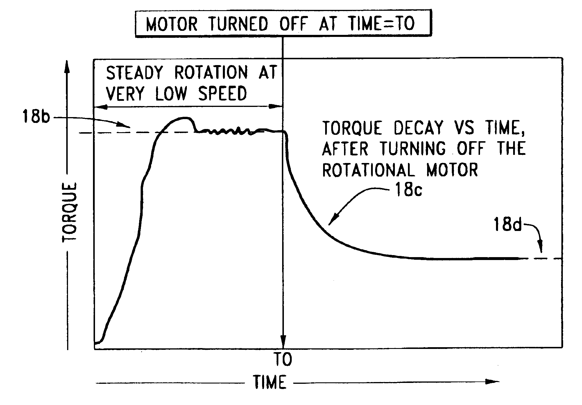
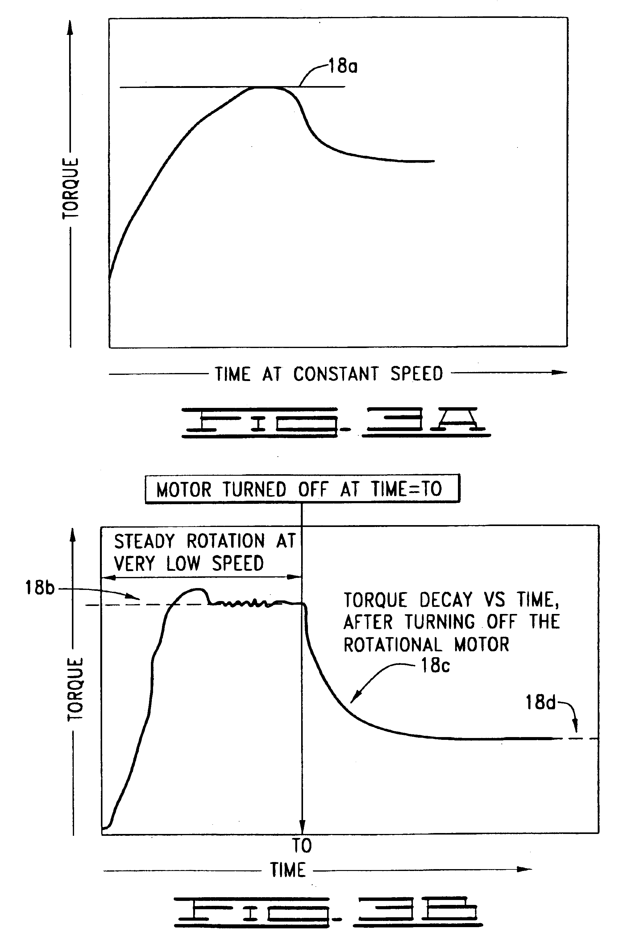
These conventional oil field viscometers are, however, not sufficiently sensitive to measure the low torque values for either DM method.
Additionally, these field viscometers may not be equipped with the capability of controlling a constant rotational speed less than unity.
Error can also be induced by slippage that occurs between the smooth surface of a bob and the fluid, especially when particulates are present.
This slippage may cause significant error when measured torques are quite low.
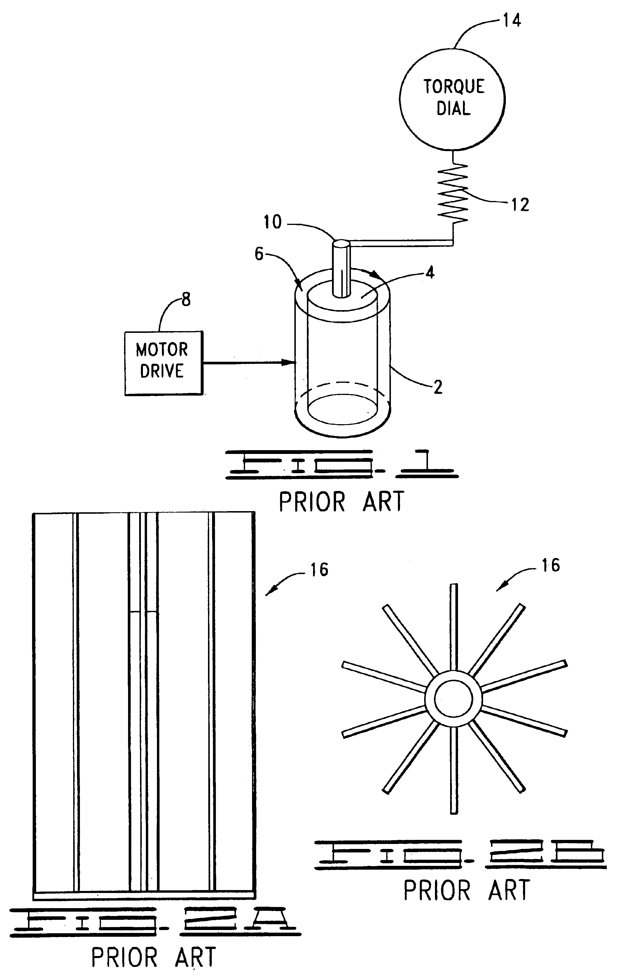
However, conventional oil field Couette viscometers have three limitations that prevent their use with a vane device for measuring yield stress: their torque responsive springs are not sensitive enough for accurate detection; many such viscometers are not equipped with capabilities of operating at less than one rpm; and the vane device works best if it is attached to a rotating shaft and lowered into a large sample of fluid, without the use of the outer sleeve.
When attempts were made to adapt the vane in FIGS. 2A and 2B to a typical oil field viscometer, the device was not sensitive enough to detect low levels of YP, such as less than ten pascals (Pa).
The problem is the combination of sensitivity of the torque spring and the fact that the vane remains stationary, while the sleeve rotates.
In the case of cements with added particulates and fracturing fluids with proppant, conventional Couette viscometers are not normally capable of accurately measuring rheogram data nor YP due to two key constraints: the, gap between the bob and sleeve is too small, thus particles easily jam and lock-up the viscometer; and the rotation of the sleeve creates centrifugal forces that cause the particles to migrate and stratify in the radial direction.
Both of these physical phenomena cause unacceptable error.

Method used


Image

  • Yield point adaptation for rotating viscometers
  • Yield point adaptation for rotating viscometers
  • Yield point adaptation for rotating viscometers

Examples


Embodiment Construction

The apparatus for measuring yield stress of a fluid composition in accordance with the present invention comprises a rotating viscometer that includes a driven portion, a responsive body, a “standard” (that is, standard for a conventional Couette or rotating viscometer) spring and a plurality of fins or vanes (referred to herein as fins). These fins have predetermined shapes and the fins are disposed in the rotating viscometer such that the rotating viscometer and the standard spring of the rotating viscometer are sensitive to detect yield stress of a test fluid composition in response to a selected rotation imparted to the driven portion of the rotating viscometer. The standard spring of the rotating viscometer is connected to the responsive body of the rotating viscometer, which responsive body has at least a portion of the fins on it. In the illustrated embodiment of FIGS. 4 and 5, a set of intermeshing fins or vanes are attached to a modified bob and modified sleeve that easily ...


PUM

PropertyMeasurementUnit
yield pointaaaaaaaaaa
torqueaaaaaaaaaa
speedaaaaaaaaaa

Abstract

A conventional Couette viscometer is transformed to measure yield point, also known as yield stress, and other rheology of various fluids, including ones with particulates. A rotating viscometer includes a driven portion, a responsive body, a standard spring, and a plurality of fins. The fins have predetermined shapes such that the rotating viscometer and the standard spring, connected to the responsive body having at least a portion of the fins, are sensitive to detect yield stress of a test fluid composition in response to a selected rotation imparted to the driven portion. A method of measuring yield stress includes operating a standard rotating viscometer modified with a plurality of intermeshing fins such that a standard spring of the standard rotating viscometer responds to a torque that is related to yield stress and that is imposed by a stressed test material on a portion of the fins connected to the spring.

Description

BACKGROUND OF THE INVENTIONThis invention relates generally to determining the yield point, also known as yield stress, of a fluid as well as conventional shear stress versus shear rate viscosity data. More particularly, this invention relates to adapting a conventional bob and sleeve viscometer to provide direct measurement of a material's yield stress.Ascertaining rheological properties of fluids used in drilling and completing oil and gas wells normally requires that “shear stress-shear rate” data (referred to as “rheogram data”) be collected via a viscometric device. Then by selecting an a priori viscosity model, the data can be analyzed, usually by statistical means, to determine “best fit” model parameters that are the quantitative estimates for specific rheological properties, including yield stress. Common models used in the oil and gas industry include:Newtonian fluid, defined as: μ=[τγ]=constant[1]Power Law, defined as: ηPL=[τγ]=Kp⁡(γ.)np-1[2]Bingham Plastic, defined as: η...

Claims


Application Information

Patent Timeline
Patent Type & Authority Patents(United States)
IPC IPC(8): G01N11/10G01N11/14
CPCG01N11/14
Inventor JOHNSON, JOHNNY W.MORGAN, RONNIE G.
Owner HALLIBURTON ENERGY SERVICES INC
Why Eureka
Try Eureka