Cutting machine with built-in miter cutting feature

a technology of miter cutting and cutting machine, which is applied in the field of cutting machine, can solve the problems of limited lifting angle of work piece, uneven bevel cutting, and permanent damage to work pi

Inactive Publication Date: 2005-04-05
LEE WY PERON
View PDF9 Cites 95 Cited by
  • Summary
  • Abstract
  • Description
  • Claims
  • Application Information

AI Technical Summary

Benefits of technology

A main object of the present invention is to provide a cutting machine with built-in miter cutting feature that accommodates cutting work in at an angle or a bevel for precisely cutting on a work piece.
Another object of the present invention is to provide a cutting machine with built-in miter cutting feature, wherein the cutting head of the cutting machine can be rigidly supported at a 45° degrees with respect to the cutting table for providing a bevel cut on the work piece.
Another object of the present invention is to provide a cutting machine with built-in miter cutting feature, wherein the cutting head can be finely tuned to obtain a precise 45° degrees with respect to the cutting table.
Another object of the present invention is to provide a cutting machine with built-in miter cutting feature, wherein a projectile angle of the cutting head with respect to the cutting table can be finely adjusted so as to provide a precise cut on the work piece.
Another object of the present invention is to provide a cutting machine with built-in miter cutting feature, wherein the cutting head is locked at either a normal vertical position or an inclined position, so as to prevent an unwanted lateral movement of the cutting blade during cutting process.
a pivot mean for pivotally connecting the outer side of the head platform with the platform pivot arm in a perpendicular manner that the cutting head is able to be rotated about the head platform to a slanted position by lifting an inner side of the head platform up from the platform support frame;

Problems solved by technology

However, the angle of the work piece to be lifted up is limited by the size of the miter block.
Sometime, when the miter block fails to correctly place in position, an uneven bevel cut may happen or a permanent damage may be caused to the work piece.
In general the work piece to be cut needs to be placed up side down for proper angle cutting, that may cause chipping at the work piece's cutting edge.
However, due to the mechanical connection of the cutting head such as screwing and welding, the cutting head may not be set and locked at exactly 45° degrees with respect to the cutting table.
However, the conventional cutting machine fails to provide a fine adjustment to tune the inclination of the cutting head which is 45° degrees with respect to the cutting table.

Method used


Image

  • Cutting machine with built-in miter cutting feature
  • Cutting machine with built-in miter cutting feature
  • Cutting machine with built-in miter cutting feature

Examples


Embodiment Construction

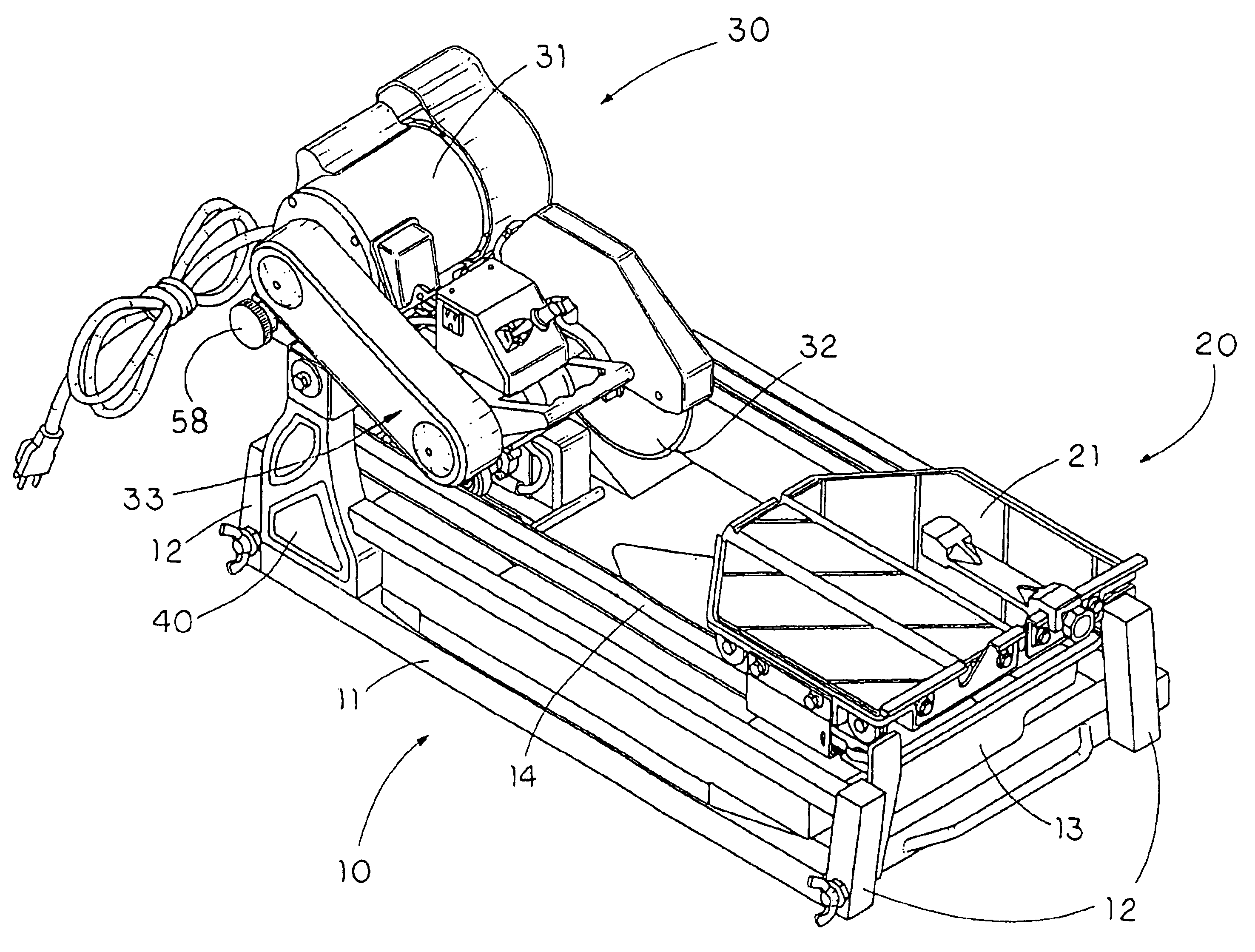
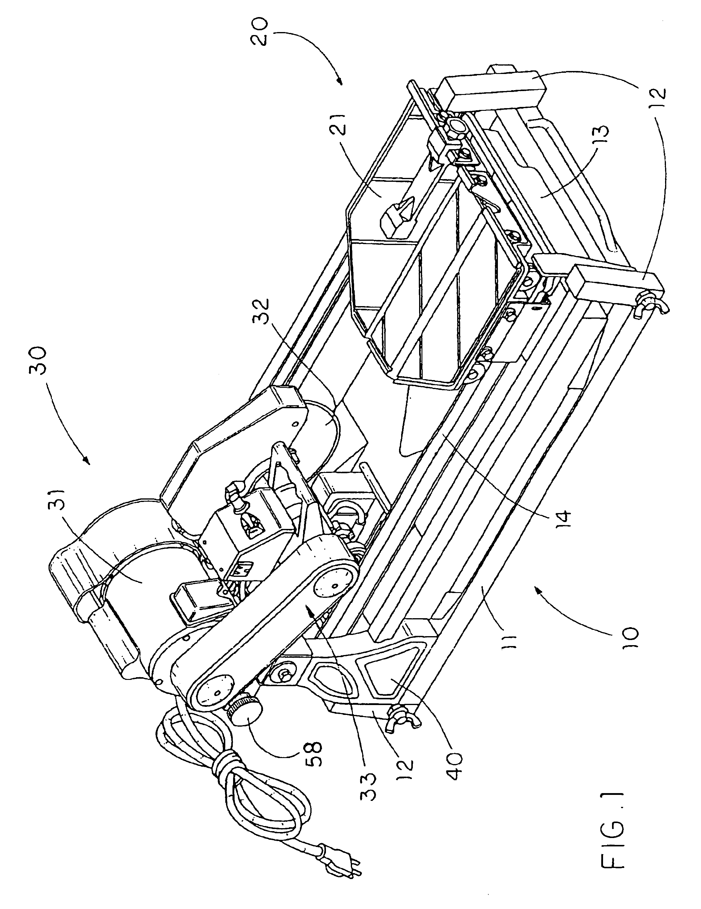
Referring to FIGS. 1 through 4 of the drawings, a cutting machine with built-in miter cutting feature, which is specifically designed for ceramic and masonry work pieces such as tiles, according to a preferred embodiment of the present invention is illustrated. The cutting machine comprises a table frame 10, a cutting table 20 slidably mounted on the table frame 10, a cutting head 30, and a cutting head support bracket 40 affixed at one side of the table frame 10 for supporting the cutting head 30 above the cutting table 20.

The cutting head 30 comprises a motor 31, a cutting blade 32, and a transmission means 33 for transmitting a rotating power of the motor 31 to drive the cutting blade 32 to rotate.

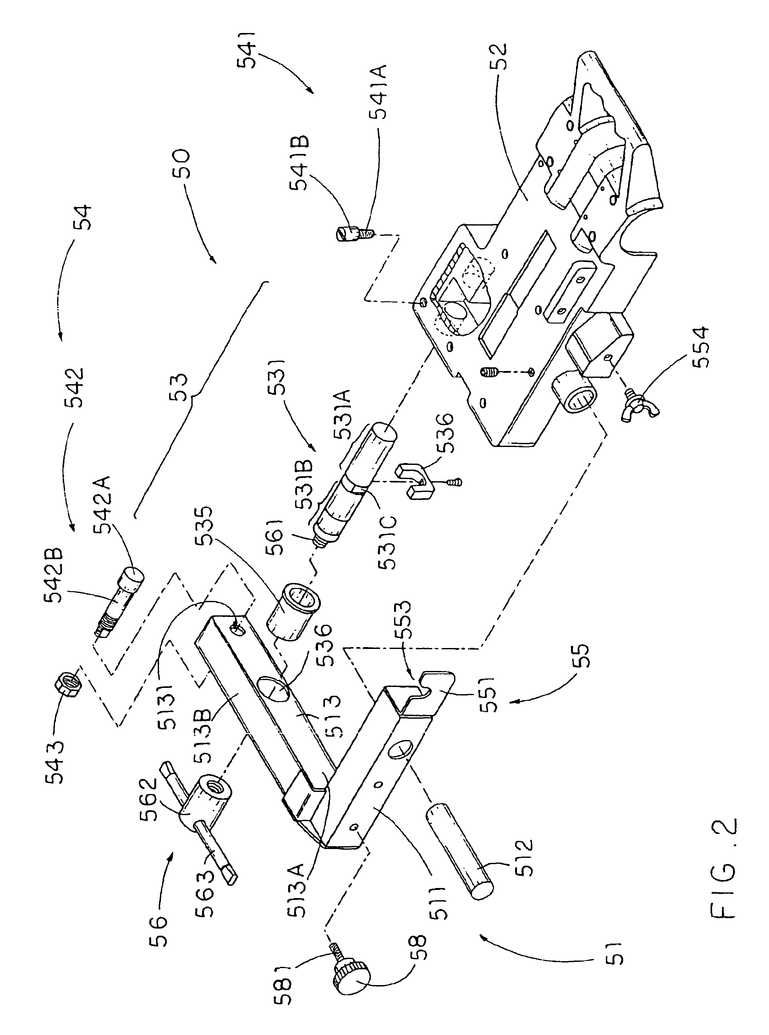
The cutting machine further comprises a miter cutting arrangement 50, which is provided between the cutting head support bracket 40 and the cutting head 30, comprises a platform support frame 51 which comprises a platform support arm 511, means 512 for longitudinally mounting the platfo...


PUM

PropertyMeasurementUnit
angleaaaaaaaaaa
inclination angleaaaaaaaaaa

Abstract

A miter cutting arrangement for a cutting machine is provided to accommodate cutting work at an angle or a bevel for precisely cutting on a work piece. It includes a platform support arm longitudinally mounting to a cutting head support bracket, a platform pivot arm transversely extended from the platform support arm, a head platform pivotally connected with the platform pivot arm to support a motor, a miter supporting unit, and a locker device for selectively locking the cutting head at the normal position and the slanted position. The miter supporting unit includes a miter support provided at an outer side of the head platform and a miter stopper provided at an outer end of the platform pivot arm to block the miter support when the head platform is rotated at the slanted position.

Description

BACKGROUND OF THE PRESENT INVENTION1. Field of InventionThe present invention relates to a cutting machine, and more particularly to a cutting machine with a built-in miter cutting feature which is adjusted accommodate cutting work at an angle or a bevel for precisely cutting on a work piece such as ceramic tile, marble, and the like.2. Description of Related ArtsA conventional cutting machine is commonly used in the construction industry for shaping and cutting material such as ceramic tile, marble, and natural stone. The conventional cutting machine comprises a cutting table supported on a table frame, and a cutting head overhanging the cutting table with a circular saw blade which is powered by an electric motor. The electric motor is directly mounted on the cutting head for driving the saw blade to rotate through a transmission means.Conventionally, the saw blade is rigidly installed perpendicularly to the cutting table so that when a work piece is placed horizontally to the cut...

Claims


Application Information

Patent Timeline
Patent Type & Authority Patents(United States)
IPC IPC(8): B23D45/02B28D1/04B23D45/00B26D7/26B27B5/24B27B5/00B28D1/02
CPCB23D45/02B28D1/047B27B5/24B26D7/2635Y10T83/242Y10T83/263Y10T83/293Y10T83/6608Y10T83/7705Y10T83/7726Y10T83/773Y10T83/8763Y10T83/8773Y10T83/9488
Inventor LEE, WY PERON
Owner LEE WY PERON
Why Eureka
Try Eureka