Woven preform for structural joints

Inactive Publication Date: 2005-04-05
LOCKHEED MARTIN CORP
View PDF57 Cites 110 Cited by
  • Summary
  • Abstract
  • Description
  • Claims
  • Application Information

AI Technical Summary

Benefits of technology

The fill fibers follow a weave sequence that carries them through a portion of the base, then into the legs, then through the opposite portion of the base, and back through the entire base to return to the starting point of the fill tow. The legs are connected at a symmetrical, distributed-column intersection, with an odd number of columns of warp fibers being located between the legs. This allows for symmetry about a central plane in the weave pattern, providing symmetrical load-carrying ability. The outer ends of the base and legs preferably have tapers formed from terminating layers of warp fibers in a stepped pattern.
Tracer fibers, comprising a colored strand and an x-ray opaque strand, are located in the preform at selected locations as a

Problems solved by technology

However, these prior-art preforms have been limited in their ability to withstand high out-of-plane loads, to be woven in an automated loom process, and to provide for varying thickness of portions of the preform.

Method used


Image

  • Woven preform for structural joints
  • Woven preform for structural joints
  • Woven preform for structural joints

Examples


Embodiment Construction

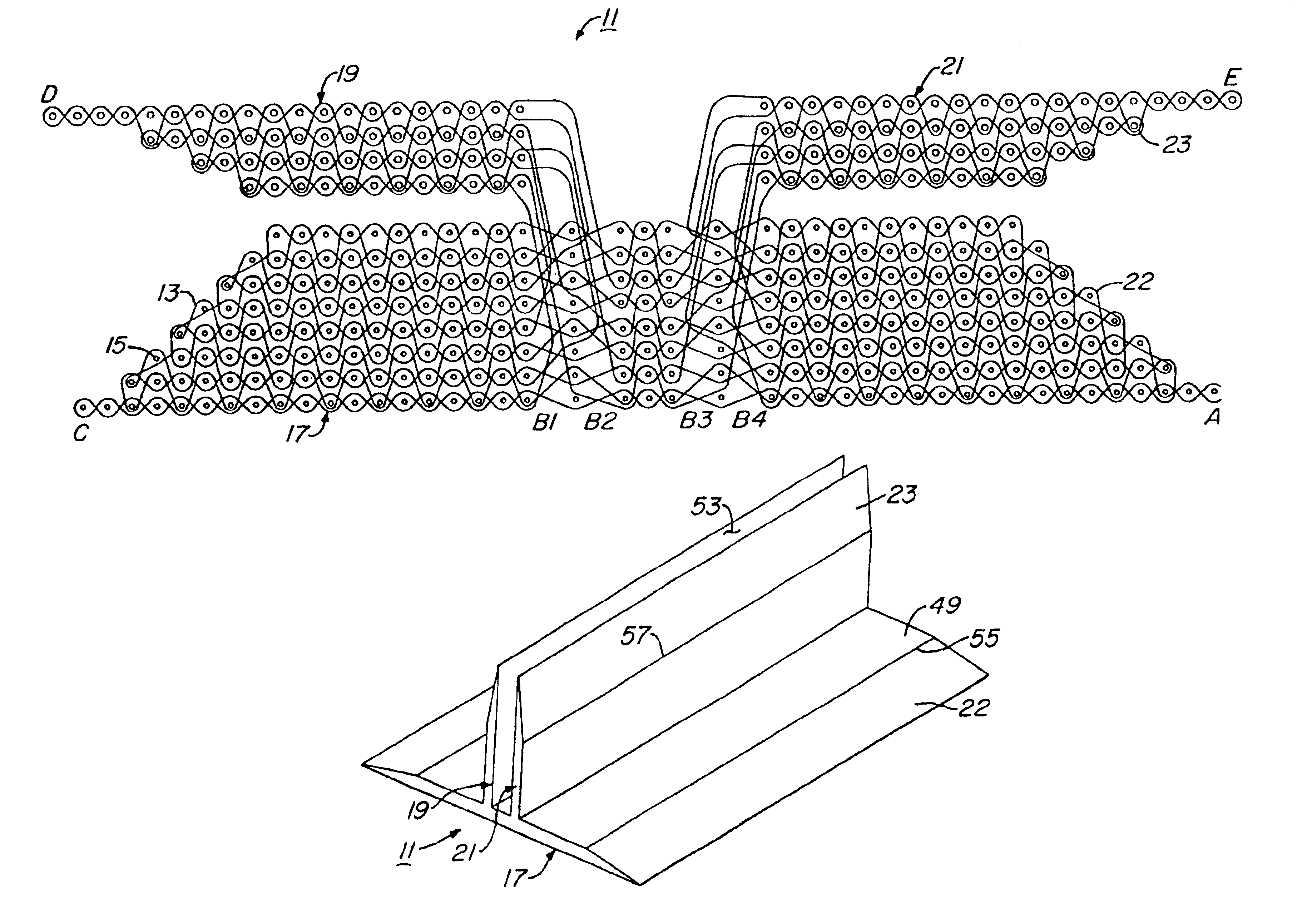
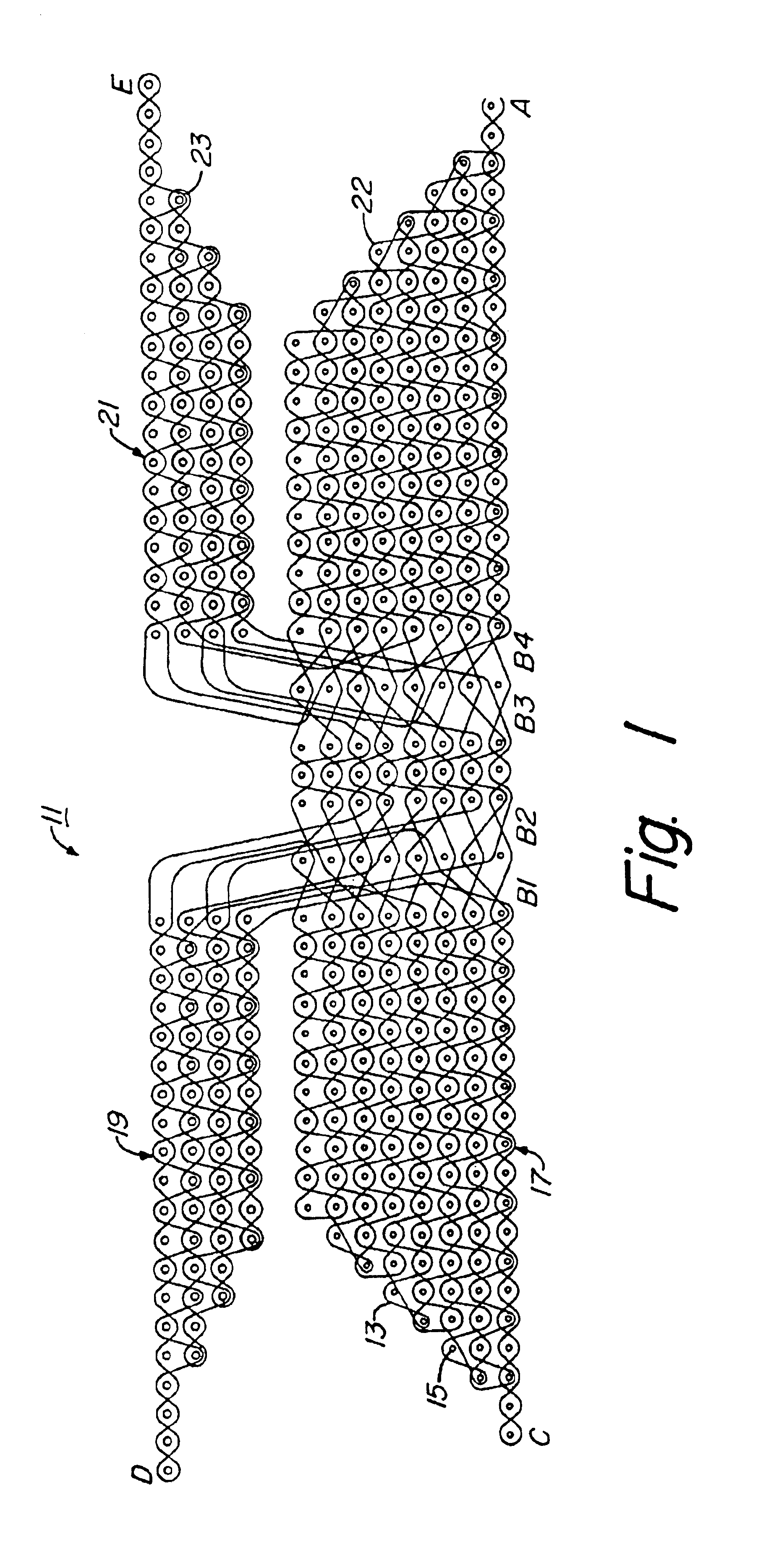
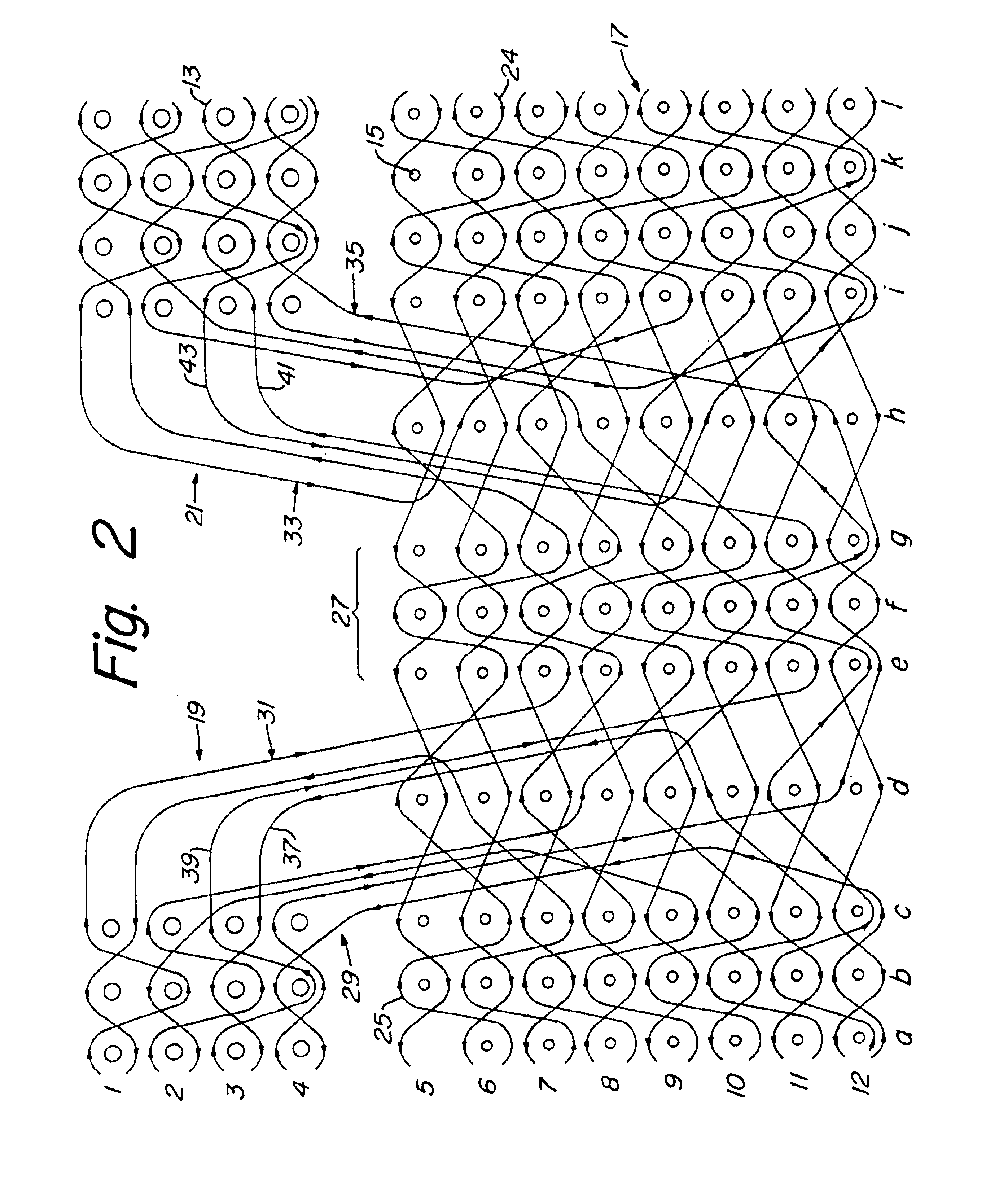
FIGS. 1 through 4 illustrate a preferred embodiment of a three-dimensional preform 11. Preform 11 is formed by weaving one or more fill fibers 13 in a tow pattern through a plurality of warp fibers 15, warp fibers 15 extending perpendicularly to the plane of the tow pattern. In FIGS. 1 through 3, fill fibers 13 are shown in the viewing plane, whereas warp fibers 15 are shown as perpendicular to the viewing plane. FIG. 1 illustrates the complete tow pattern used to form pi-shaped preform 11, whereas FIGS. 2 and 3 illustrate portions of the pattern of FIG. 1. Fibers 13, 15 are shown as spaced apart in the schematic views of the architecture, though fibers 13, 15 are compacted together when actually woven into a completed preform 11.

All warp fibers 15 in preform 11 are generally parallel to each other, with slight undulations along the longitudinal length of each fiber 15, and are arranged in generally vertical columns. Preform 11 is preferably woven from materials used for typical com...


PUM

PropertyMeasurementUnit
Coloraaaaaaaaaa
Areaaaaaaaaaaa
Symmetryaaaaaaaaaa

Abstract

A preform for structural joints has a three-dimensional weave architecture with fill fibers woven to provide layer-to-layer interlocking of layers of warp fiber as well as interlocking of fibers within each layer. At least two legs extend from a base, the base and legs each having at least two layers of warp fibers. The legs are connected at a symmetrical, distributed-column intersection, with an odd number of columns of warp fibers being located being the legs. The outer ends of the base and legs preferably have tapers formed from terminating layers of warp fibers in a stepped pattern. Tracer fibers that include a colored strand and an x-ray opaque strand are woven into the preform at selected locations as a warp fiber. The tracer fibers allow for identification of a selected location or a selected portion of the preform through visual inspection or by x-ray image.

Description

BACKGROUND OF THE INVENTION1. Field of the InventionThis invention generally relates to woven preforms and particularly relates to woven preforms used in bonding of components at structural joints.2. Description of the Related ArtWhen joining components in a structural joint, layers of fabric infused with a polymer resin can be used to join the components. For example, two components are brought to the desired positions and orientation, and layers of composites are adhered to the outer surfaces of the components: one portion of the fabric adhering to one component, another portion adhering to the other component. Multiple layers of fabric are stacked to increase the strength of the joint and to form a desired radius of curvature at the intersection.While this method works, the joint can be improved by having fibers that extend through the intersection of the components, connecting the composite layers on both sides of the joint. A three-dimensional (3-D), woven, textile preform prov...

Claims


Application Information

Patent Timeline
IPC IPC(8): B29C70/10B29C70/24D03D25/00
CPCB29C70/24B29B11/16D03D25/005Y10S139/01Y10T442/3195
Inventor SCHMIDT, RONALD P.KALSER, DAVID A.
Owner LOCKHEED MARTIN CORP
Why Eureka
Try Eureka