X-ray imaging system and x-ray imaging method

a technology of x-ray imaging and x-ray, which is applied in the field of x-ray imaging system and x-ray imaging method, can solve the problems of not being able to describe continuously changing the blade of the collimator, and achieve the effects of shortening the imaging time, improving the imaging cycle, and reducing the cost of operation

Inactive Publication Date: 2012-03-01
FUJIFILM CORP
View PDF0 Cites 150 Cited by
  • Summary
  • Abstract
  • Description
  • Claims
  • Application Information

AI Technical Summary

Benefits of technology

[0011]An object of the present invention is to provide an X-ray imaging system and an X-ray imaging method for reconstructing an X-ray tomographic image in a cross section at an arbitrary height of the subject, the X-ray imaging system and the X-ray imaging method enabling reduction in exposure dosage, shortening imaging time, and reduction of blurring of an image due to a movement of a patient by irradiating only a region of interest with X ray.
[0021]The present invention enables acquisition of X-ray images for reconstructing an X-ray tomographic image with a small exposure dosage, and improvement in imaging cycle enables shortening of the imaging time. A shortened imaging time in turn reduces blurring of images due to a movement of a patient, and reconstruction of an X-ray tomographic image is achieved from clearer X-ray images.

Problems solved by technology

However, the literature does not describe continuously varying the collimator blades according to the position of the X-ray source to ensure that the X-ray images on the FPD are rectangular regardless of the position of the X-ray source.

Method used


Image

  • X-ray imaging system and x-ray imaging method
  • X-ray imaging system and x-ray imaging method
  • X-ray imaging system and x-ray imaging method

Examples


Embodiment Construction

[0027]The X-ray imaging system of the invention for implement an X-ray imaging method of the invention will be described in detail based upon the preferred embodiments illustrated in the attached drawings.

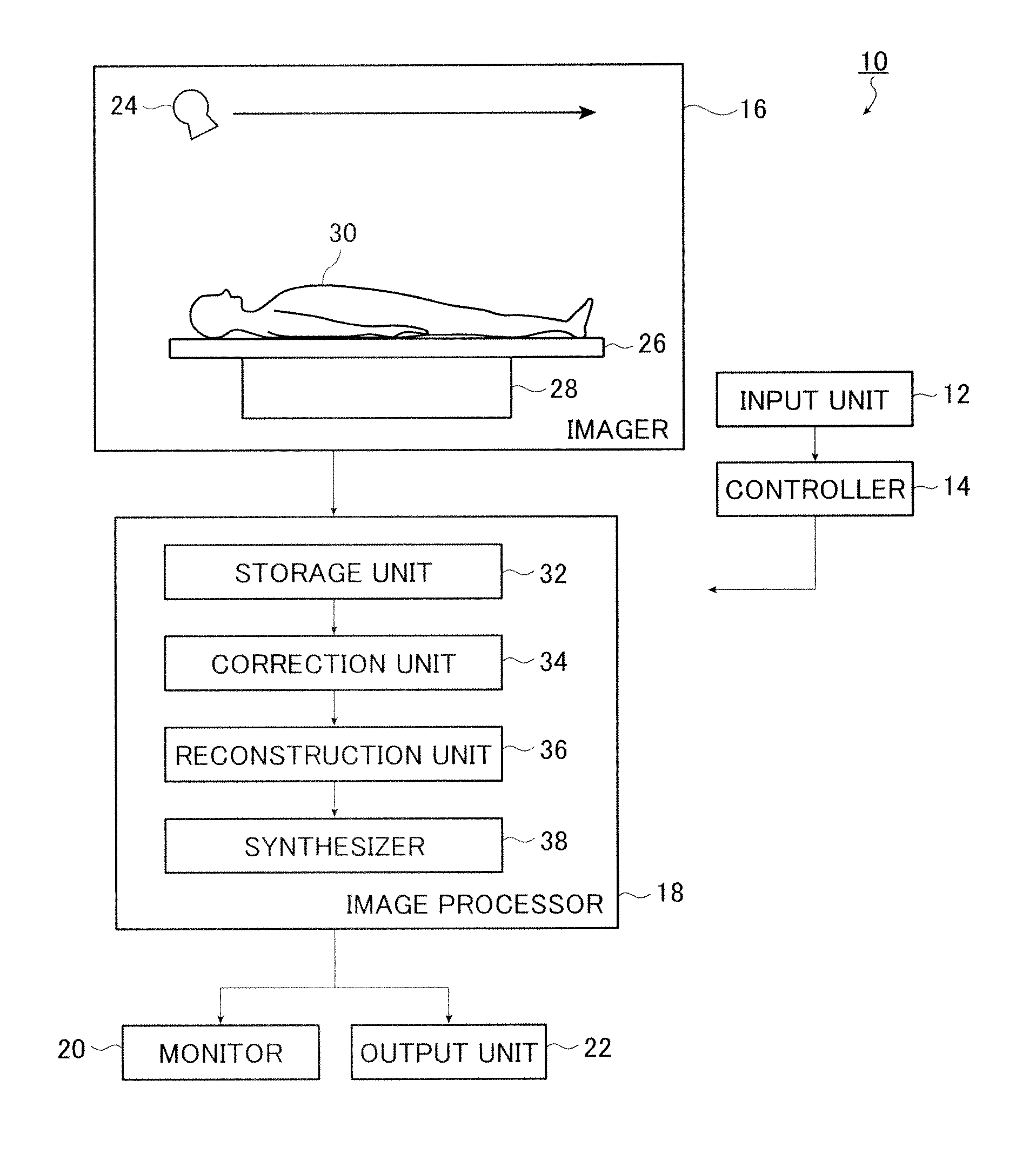
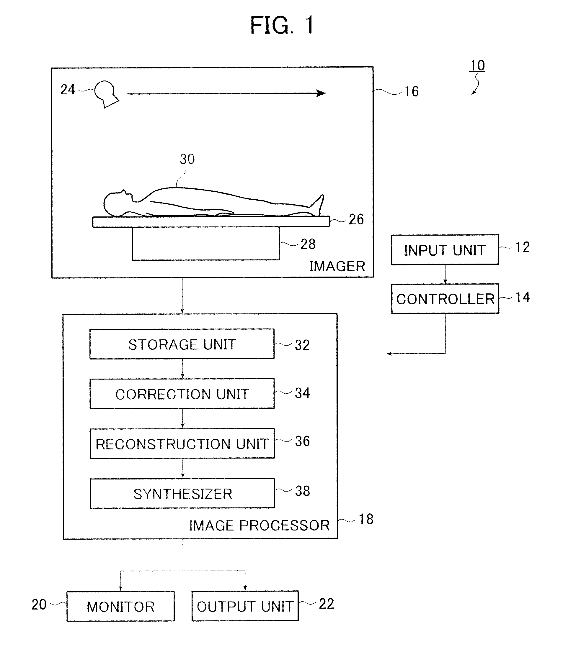
[0028]FIG. 1 is a block diagram representing a configuration of an embodiment of an X-ray imaging system according to the invention.

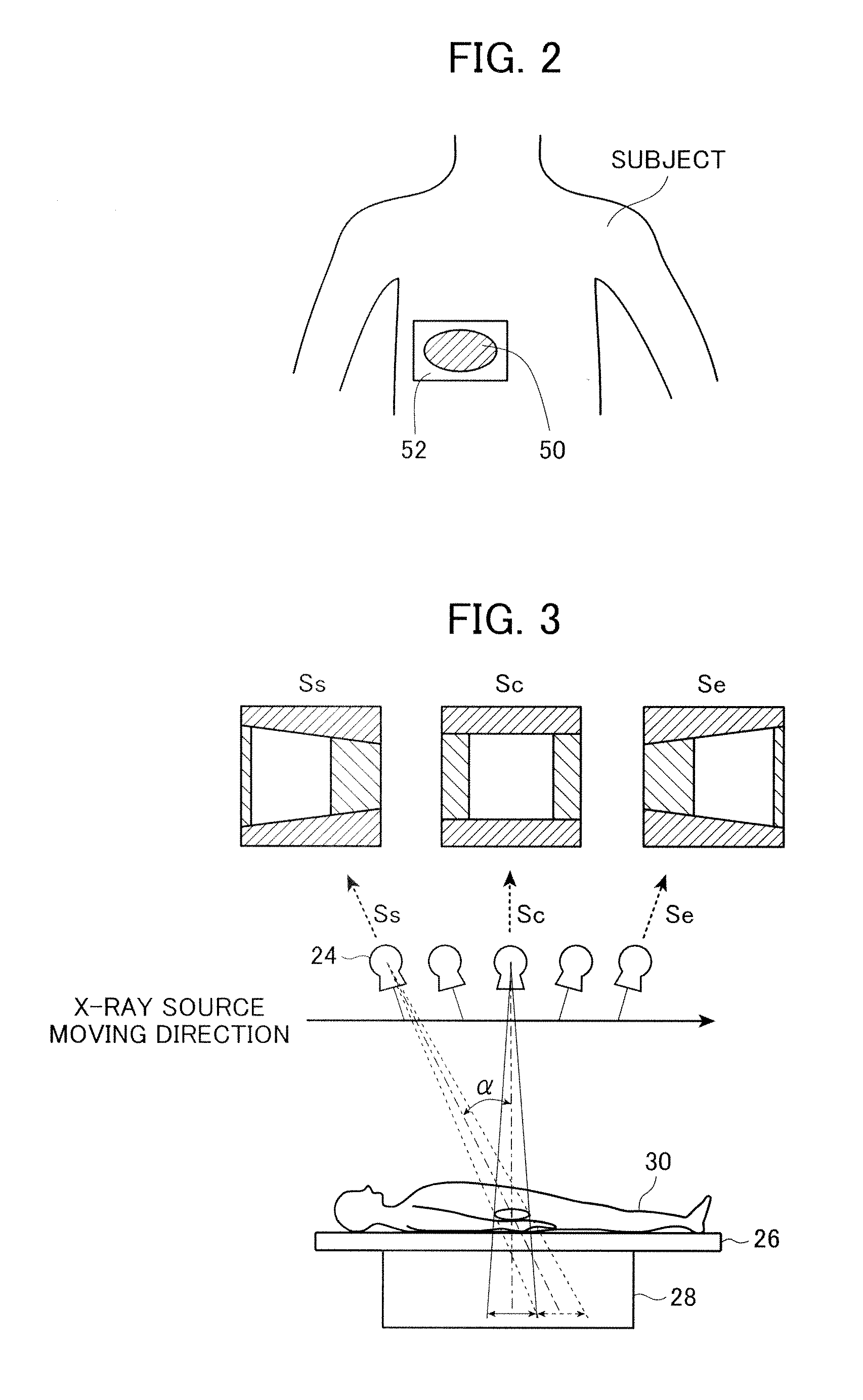
[0029]An X-ray imaging system 10 illustrated in FIG. 1 acquires images of a subject 30 such as a human body by tomosynthesis imaging (X-ray imaging) and reconstructs an X-ray tomographic image in a cross section located at an arbitrary height of the subject 30. The X-ray imaging system 10 comprises an input unit 12, a controller 14, an imager 16, an image processor 18, a monitor 20, and an output unit 22.

[0030]The input unit 12 is provided to enter various instructions including but not limited to an instruction to start imaging and may be configured by a mouse, a keyboard, etc. The input unit 12 produces an instruction signal, which is received by the...


PUM


Abstract

An X-ray imaging system is for irradiating a subject with X ray from an X-ray source at a plurality of different angles to acquire X-ray images, and reconstructing an X-ray tomographic image from the X-ray images. The system comprising a region setting unit for setting a region of interest on a pre-shot image or a previously acquired X-ray tomographic image, an imaging control unit for continuously varying an aperture formed by collimator blades according to a position of the X-ray source to image the region of interest and acquiring projection data of the X-ray images in accordance with the position of the X-ray source, and an image reconstructing unit for reconstructing the X-ray tomographic image from the projection data of the X-ray images of the region of interest. The aperture formed by the collimator blades are varied so that all the X-ray images formed on the X-ray detector is rectangular regardless of the position of the X-ray source.

Description

BACKGROUND OF THE INVENTION[0001]The present invention relates to an x-ray imaging system and an x-ray imaging method for reconstructing an X-ray tomographic image of a subject in a cross section at an arbitrary height thereof using projection data of X-ray images acquired by tomosynthesis imaging.[0002]An X-ray imaging system for tomosynthesis imaging irradiates a subject with X ray at different angles as the X-ray source is moved in one direction and detects the X ray with which the subject has been irradiated using a flat panel X-ray detector (FPD) to achieve acquisition of projection data of X-ray images of the subject taken at different angles in a single imaging operation. Then the process proceeds to image processing using the projection data of the X-ray images to reconstruct an X-ray tomographic image in a cross section of the subject at an arbitrary height thereof.[0003]Now, reconstruction of an X-ray tomographic image will be described.[0004]In tomosynthesis imaging, the ...

Claims


Application Information

Patent Timeline
Patent Type & Authority Applications(United States)
IPC IPC(8): A61B6/03
CPCA61B6/025A61B6/06A61B6/4233G06T2211/436G21K1/04G21K1/046G06T11/006A61B6/5205
Inventor KOISHI, TAKESHI
Owner FUJIFILM CORP
Why Eureka
Try Eureka