
Methods and apparata for precisely dispensing microvolumes of fluids

a technology of fluids and microvolumes, applied in the field of fluid microvolume dispensing methods and apparatas, can solve the problems of complexity, cost, and size of piezoelectric ring/tube nozzles, and achieve the effects of less construction cost, easy cost-free formation, and greater inner passage diameter

Inactive Publication Date: 2005-04-05
WISCONSIN ALUMNI RES FOUND
View PDF22 Cites 40 Cited by
  • Summary
  • Abstract
  • Description
  • Claims
  • Application Information

AI Technical Summary

Benefits of technology

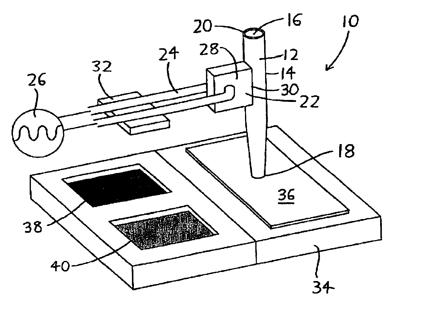
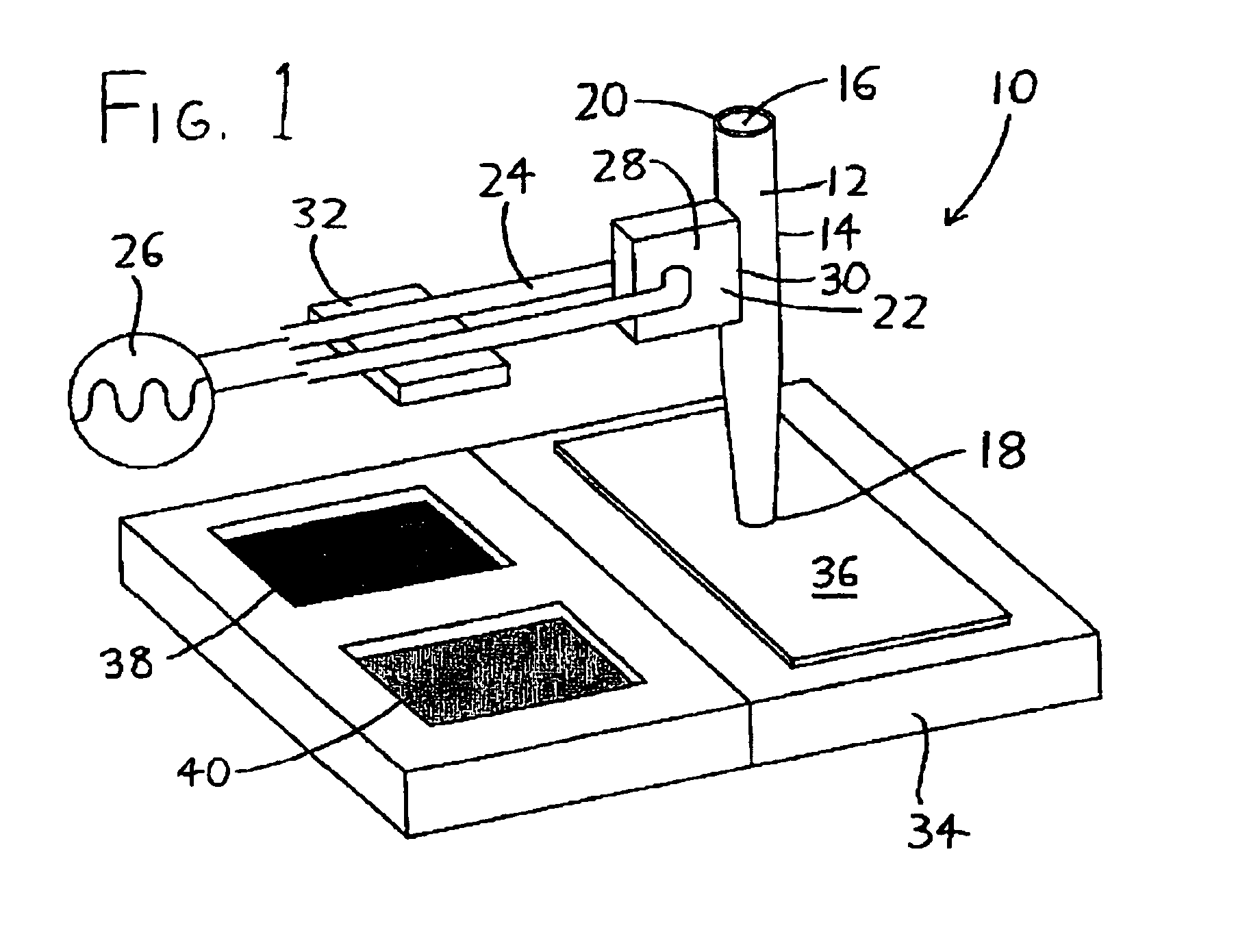
An ultrasonic actuator such as a piezoelectric element is then coupled to a portion of the nozzle's circumference, as by simply bonding the ultrasonic element onto the outer surface of the nozzle so that it extends from a portion of the outer surface's circumference. The ultrasonic actuator therefore does not encircle the nozzle and compress it about its circumference when actuated. The power leads for the ultrasonic actuator may be provided in the form of conducting leads (such as insulated or uninsulated wires) which extend from the ultrasonic actuator, and which serve as the support for the nozzle to maintain it in a desired location. If elastically flexible conducting leads support the nozzle, they may usefully serve as an elastic mount for the nozzle which will yield if the nozzle is advanced against a substrate or other object, and which will also help to damp vibrations from the nozzle (and its ultrasonic actuator) to the surrounding structure.
Another advantage is provided where the conducting leads for the ultrasonic actuator are used to support the nozzle with respect to the substrate. Since the leads may provide a flexible mount for the nozzle, allowing the dispensing end of the nozzle to advance into contact with the substrate (with further advancing of the nozzle simply resulting in elastic yielding of the leads), the leads provide an advantageous means of accommodating imprecise spacing of the nozzle's dispensing end from the substrate (which is often encountered owing to variations in the substrate's height across its surface). Since the apparatus is capable of depositing fluid even when the nozzle's dispensing end is in contact with a surface, one can be assured of at least relatively uniform spot sizes between successive deposition events by simply advancing the nozzle's dispensing end onto the surface of the substrate during each event.

Problems solved by technology

However, quill pen dispensation suffers from the disadvantage that over time, as quill tips (which can cost as much as several hundred dollars per tip) degrade, spot sizes grow and become more irregular.
The arrangement is somewhat bulky owing to the need to mount die inner needle within tie outer needle in such a manner that vibrational coupling between the two is minimized.
A disadvantage of the prior piezoelectric ring / tube nozzles is their size, complexity, and cost.
Cost and complexity are issues owing to the need to manufacture a piezoelectric tube / ring wherein a nozzle can be inserted with close coupling between the structures.
Size is problematic since it will often be useful to provide multiple adjacent nozzles which dispense onto the same substrate (each often depositing a different fluid), thereby allowing rapid dispensation of multiple spots or other features.
However, looking to nozzle arrangements such as those shown in FIG. 1 of U.S. Pat. No. 6,232,129, and FIG. 2 of U.S. Pat. No. 6,001,309, there are apparent difficulties in providing such nozzles sufficiently closely spaced in an array that they can be simultaneously used to dispense fluids on the same small substrate (e.g., on the same microarray slide).
Additional difficulties would be encountered with nozzle arrays because the size of deposited spots may vary in accordance with the distance of the dispensing end of each nozzle from the substrate, and if the heights of the various nozzles are not precisely aligned so that their dispensing ends are spaced at the same distance from the substrate's surface, the spot sizes produced by the various nozzles will vary.
It might instead be possible to use only a single nozzle to sequentially deposit different fluids on a substrate, with the nozzle being interchanged between fluids (and rinsed between changes), but this approach leads to a significant increase in process time and can also result in unnecessary waste where the fluid being deposited is scarce.
The piezoelectric ring / tube arrangement also has the disadvantage that fluid dispensation / aspiration will not be effective unless the nozzle is “primed” with fluid to such a height that the fluid rests at or near the level of the piezoelectric ring / tube, else the expansion and contraction of the piezoelectric ring will not successfully enable pumping (see, e.g., U.S. Pat. No. 6,232,129 at column 5 line 36 onward).
This implies that the foregoing arrangements may be unsuitable for use in microdispensation of fluids which are only available in extremely limited quantities, since the nozzle may need to be supplied with more fluid than is intended for dispensation owing to the need to prime the nozzle.

Method used


Image

  • Methods and apparata for precisely dispensing microvolumes of fluids
  • Methods and apparata for precisely dispensing microvolumes of fluids

Examples


Embodiment Construction

Referring to FIG. 1, an exemplary version of an apparatus for dispensing microvolumes of fluid onto a substrate is overall designated by the reference numeral 10. The apparatus 10 includes an elongated nozzle 12 bounded on its exterior by a nozzle outer surface 14, and bounded on its interior by a nozzle interior passage 16, which extends between a nozzle dispensing end 18 and an opposite end 20. The dispensing end 18 is preferably narrowed in comparison to the opposite end 20 so that the area of the interior passage 16 is smaller at the dispensing end 18 than at the opposite end 20.

While it is expected that the nozzles 12 could be formed with a variety of different materials using a number of different techniques, the dispensing nozzle 12 may be manufactured particularly inexpensively using a standard micropipette puller, which heats and elongates glass tubes to attain microcapillaries of desired sizes. Glass nozzles 12 of this nature having interior passages 16 with diameters betw...


PUM

PropertyMeasurementUnit
sizesaaaaaaaaaa
diametersaaaaaaaaaa
frequenciesaaaaaaaaaa

Abstract

Devices and methods for depositing fluids on substrates in patterns of spots, lines, or other features use a nozzle, which is preferably configured similarly to a micropipette, having a piezoelectric crystal or other ultrasonic actuator coupled to one of its sides. The nozzle may be charged via capillary action by dipping it into a well containing the fluid to be deposited, and may then be positioned over a desired area of a substrate, at which point activation of the ultrasonic actuator at ultrasonic frequencies will eject the fluid onto the substrate. The needle may subsequently be dipped into a well of rinsing fluid for cleaning. Spots or lines on the order of 5 micrometers width may be generated, making the invention particularly suitable for use in biological applications such as microarray production and in microelectronics applications such as the printing of organic circuitry.

Description

FIELD OF THE INVENTIONThis document concerns an invention relating generally to methods and apparata for dispensing microvolumes of fluids, and more specifically to methods and apparata for depositing very small spots, lines, or other desired patterns of fluids on substrates.BACKGROUND OF THE INVENTIONIn the fields of biotechnology and nanotechnology, it is often useful to precisely dispense very small desired quantities of fluids in some desired pattern on a substrate. As an example, in the field of nanotechnology, it can be useful to situate lines or other patterns of catalysts or nucleation agents on a substrate to ready it for the later growth or deposition of other materials at these sites. As another example, in the field of biotechnology, it is often useful to situate arrays of “spots” of oligonucleotides on glass slides or other substrates for use in the later analysis of nucleic acid sequences. At the time this document was prepared, some microarray spotters are able to acc...

Claims


Application Information

Patent Timeline
Patent Type & Authority Patents(United States)
IPC IPC(8): B01L11/00B01L3/02G01N35/10B01L99/00C40B40/06C40B60/14
CPCB01L99/00B01L3/0268B01J2219/00367B01J2219/00527B01J2219/00533B01J2219/00585B01J2219/00596B01J2219/00605B01J2219/00612B01J2219/00659B01J2219/00689B01J2219/00722B01L2300/0819B01L2300/0867B01L2400/0439C40B40/06C40B60/14G01N2035/1041B01J2219/00378B01L13/02
Inventor LARSON, BRADLEY JAMESLEE, CHUNG HOONLAL, AMITLAGALLY, MAX G.
Owner WISCONSIN ALUMNI RES FOUND
Learn More