
Method for fluid jet formation

a technology of fluid jets and jets, which is applied in the direction of metal working equipment, edge grinding machines, manufacturing tools, etc., can solve the problems of affecting the effect of fluid jets, affecting the quality of fluid jets, so as to increase the turbulence of flow

Inactive Publication Date: 2005-04-05
FLOW INT
View PDF12 Cites 22 Cited by
  • Summary
  • Abstract
  • Description
  • Claims
  • Application Information

AI Technical Summary

Benefits of technology

In one aspect of this embodiment, the pressure of the primary and / or the secondary fluid can be controlled to produce a desired effect. For example, the secondary fluid can have a generally low pressure relative to the primary fluid pressure to increase the coherence of the fluid jet, or the secondary fluid can have a higher pressure to decrease the coherence of the fluid jet. In another aspect of this embodiment, the flow of the secondary fluid can be reversed, such that it is drawn in through the exit opening of the conduit and out through the aperture.

Problems solved by technology

One drawback with conventional fluid jets is that they may tear or deform certain materials, such as fiberglass, cloth, and brittle plastics.
A further drawback is that the effectiveness of conventional fluid jets may be particularly sensitive to the distance between the substrate and the nozzle through which the fluid jet exits.
Accordingly, it may be difficult to uniformly treat substrates having a variable surface topography.
It may also be difficult to use the same fluid jet apparatus to treat a variety of different substrates.
Still a further disadvantage is that some conventional fluid jet nozzles, particularly for non-round fluid jets, may be difficult and / or expensive to manufacture.

Method used


Image

  • Method for fluid jet formation
  • Method for fluid jet formation
  • Method for fluid jet formation

Examples


Embodiment Construction

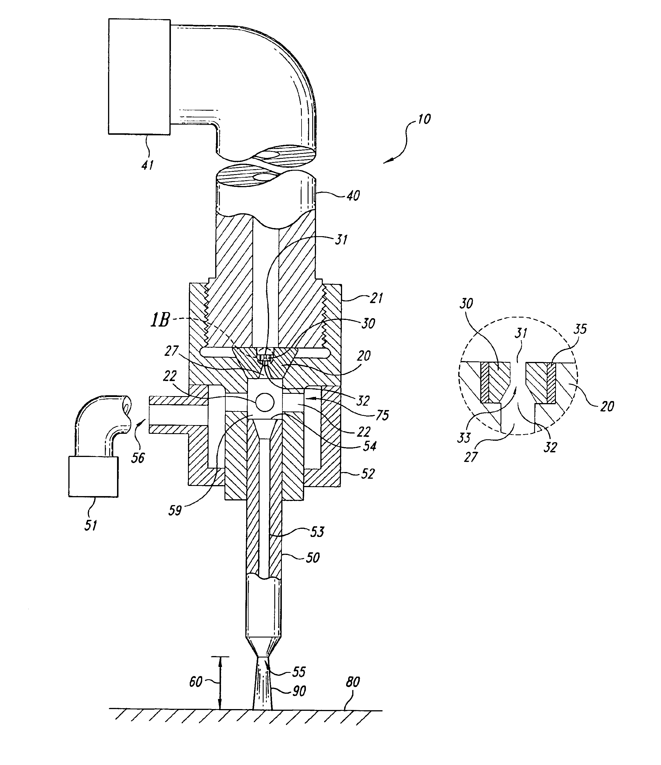
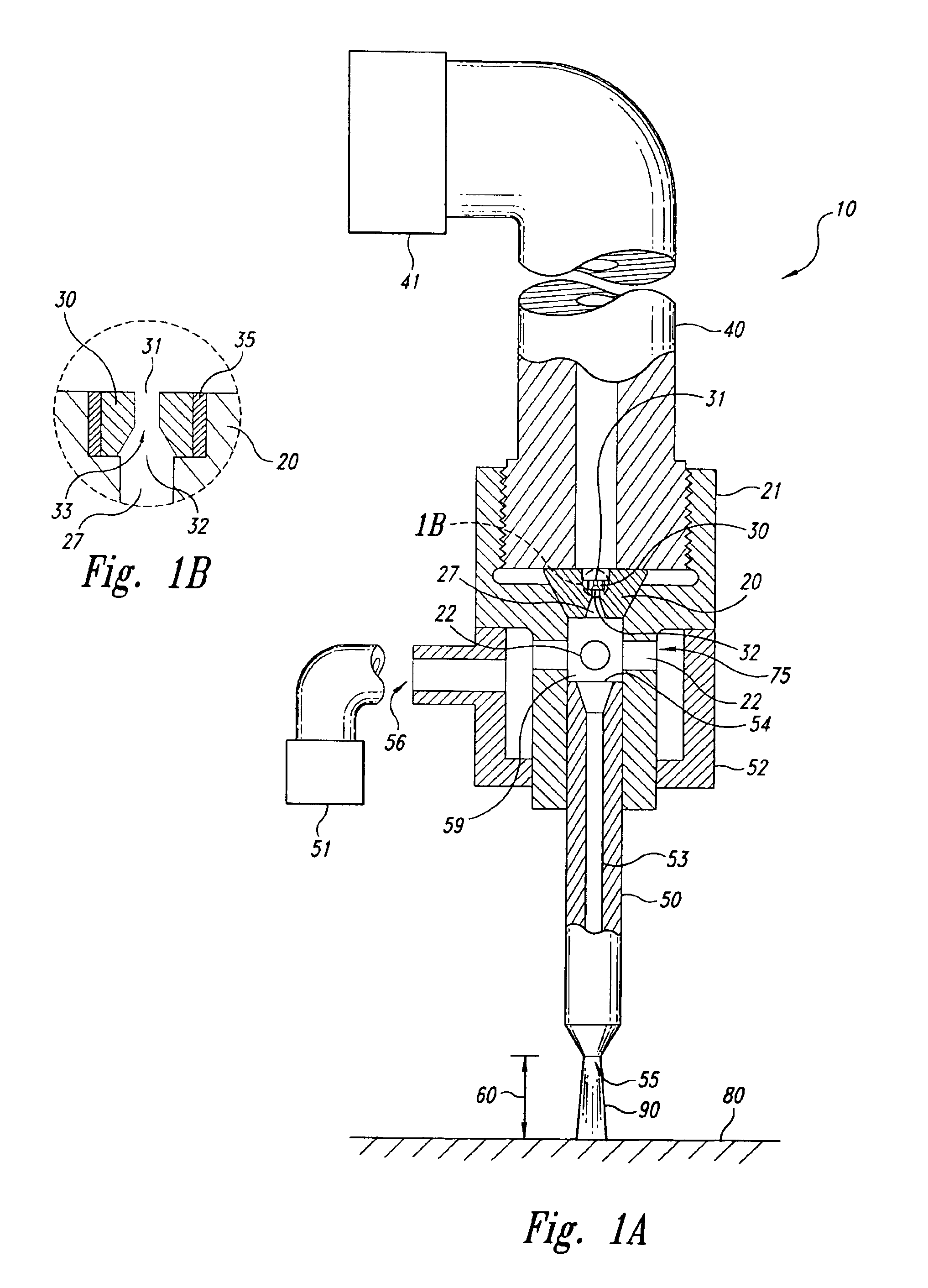
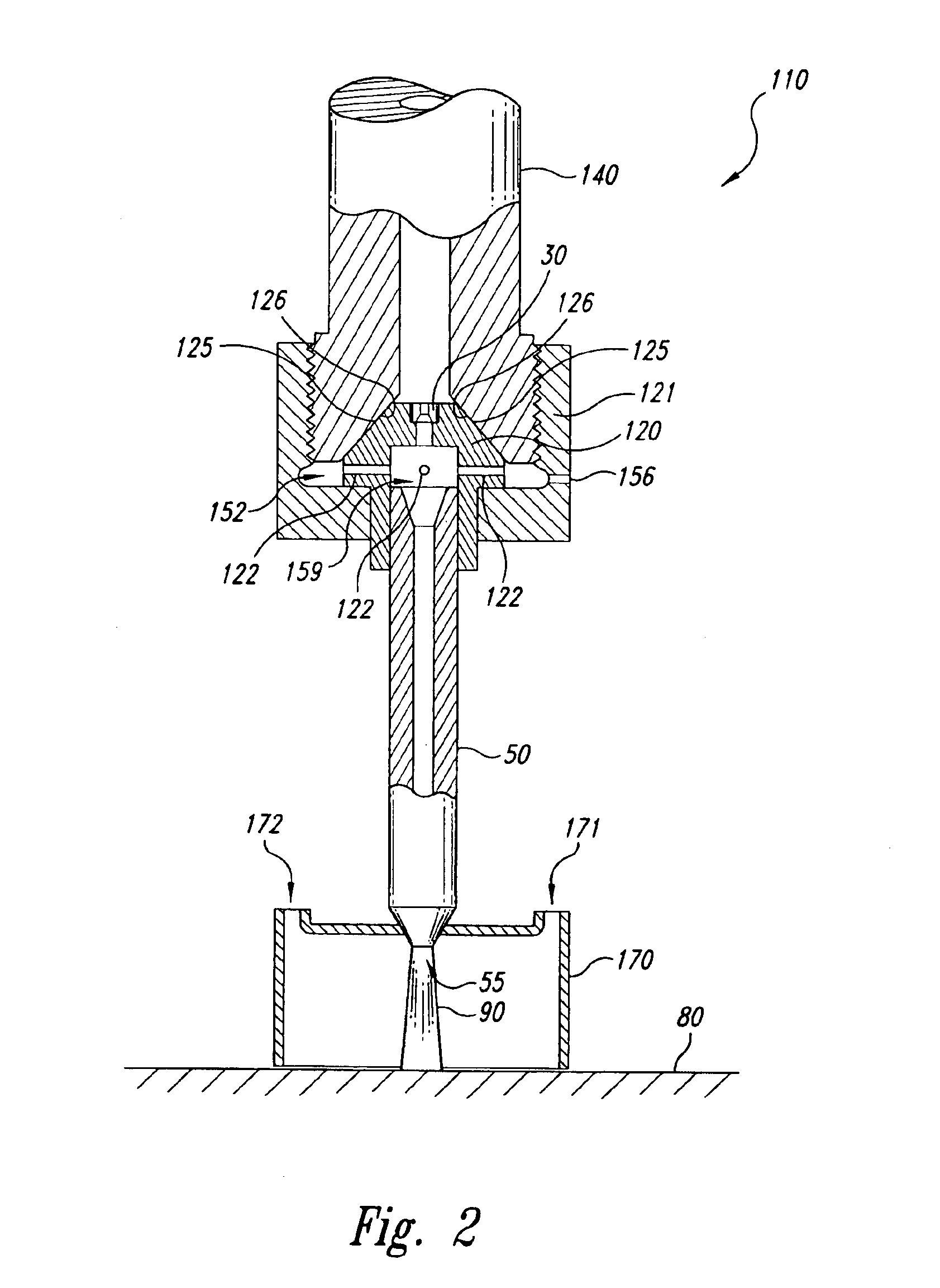
In general, conventional high pressure fluid jet methods and devices have been directed toward forcing a high pressure fluid through a nozzle orifice to produce highly focused or coherent liquid jets that can cut through or treat selected materials. By contrast, one aspect of the present invention includes controlling the coherence of the fluid jet by manipulating the turbulence level of the fluid upstream and / or downstream of the nozzle orifice. The turbulence level can be manipulated with a turbulence generator or turbulence generating means that can include, for example, a second orifice upstream of the nozzle orifice or a protrusion that extends into the flow upstream of the nozzle orifice. Alternatively, the turbulence generating means can include one or more apertures downstream of the nozzle orifice through which a second fluid is either pumped or evacuated. The pressure of the second fluid can be selected to either increase or decrease the coherence of the resulting fluid je...


PUM

PropertyMeasurementUnit
Pressureaaaaaaaaaa
Flow rateaaaaaaaaaa
Ratioaaaaaaaaaa

Abstract

A method and apparatus for controlling the coherence of a high-pressure fluid jet directed toward a selected surface. In one embodiment, the coherence is controlled by manipulating a turbulence level of the fluid forming the fluid jet. The turbulence level can be manipulated upstream or downstream of a nozzle orifice through which the fluid passes. For example, in one embodiment, the fluid is a first fluid and a secondary fluid is entrained with the first fluid. The resulting fluid jet, which includes both the primary and secondary fluids, can be directed toward the selected surface so as to cut, mill, roughen, peen, or otherwise treat the selected surface. The characteristics of the secondary fluid can be selected to either increase or decrease the coherence of the fluid jet. In other embodiments, turbulence generators, such as inverted conical channels, upstream orifices, protrusions and other devices can be positioned upstream of the nozzle orifice to control the coherence of the resulting fluid jet.

Description

BACKGROUND OF THE INVENTION1. Field of the InventionThis invention relates to methods and devices for generating high-pressure fluid jets, and more particularly, to methods and devices for generating fluid jets having a controlled level of coherence.2. Description of the Related ArtConventional fluid jets have been used to clean, cut, or otherwise treat substrates by pressurizing and focusing jets of water or other fluids up to and beyond 100,000 psi and directing the jets against the substrates. The fluid jets can have a variety of cross-sectional shapes and sizes, depending upon the particular application. For example, the jets can have a relatively small, round cross-sectional shape for cutting the substrates, and can have a larger, and / or non-round cross-sectional shape for cleaning or otherwise treating the surfaces of the substrates.One drawback with conventional fluid jets is that they may tear or deform certain materials, such as fiberglass, cloth, and brittle plastics. A fu...

Claims


Application Information

Patent Timeline
IPC IPC(8): B24C5/00B24C5/04B26F3/00D06H7/00B05B1/02B05B7/04
CPCB26F3/004B24C5/04Y10T83/0591Y10T83/2109
Inventor HASHISH, MOHAMED A.CRAIGEN, STEVEN J.SCIULLI, FELICE M.BABA, YASUO
Owner FLOW INT
Features
  • Generate Ideas
  • Intellectual Property
  • Life Sciences
  • Materials
  • Tech Scout
  • Unparalleled Data Quality
  • Higher Quality Content
  • 60% Fewer Hallucinations
Learn More