Device and a process for welding plastics profiles

Inactive Publication Date: 2005-04-05
URBAN & MASCHENBAU
View PDF10 Cites 8 Cited by
  • Summary
  • Abstract
  • Description
  • Claims
  • Application Information

AI Technical Summary

Benefits of technology

Taking as a starting point the prior art described above, the object of the invention is to provide a way of welding plastics profiles that can perform both the functional sequence of the “diagonal” feed process and also the funct

Problems solved by technology

The problem of a machine with both feed processes is in this case the large number of stops required for this.
For this construction, there is a

Method used


Image

  • Device and a process for welding plastics profiles
  • Device and a process for welding plastics profiles
  • Device and a process for welding plastics profiles

Examples


Embodiment Construction

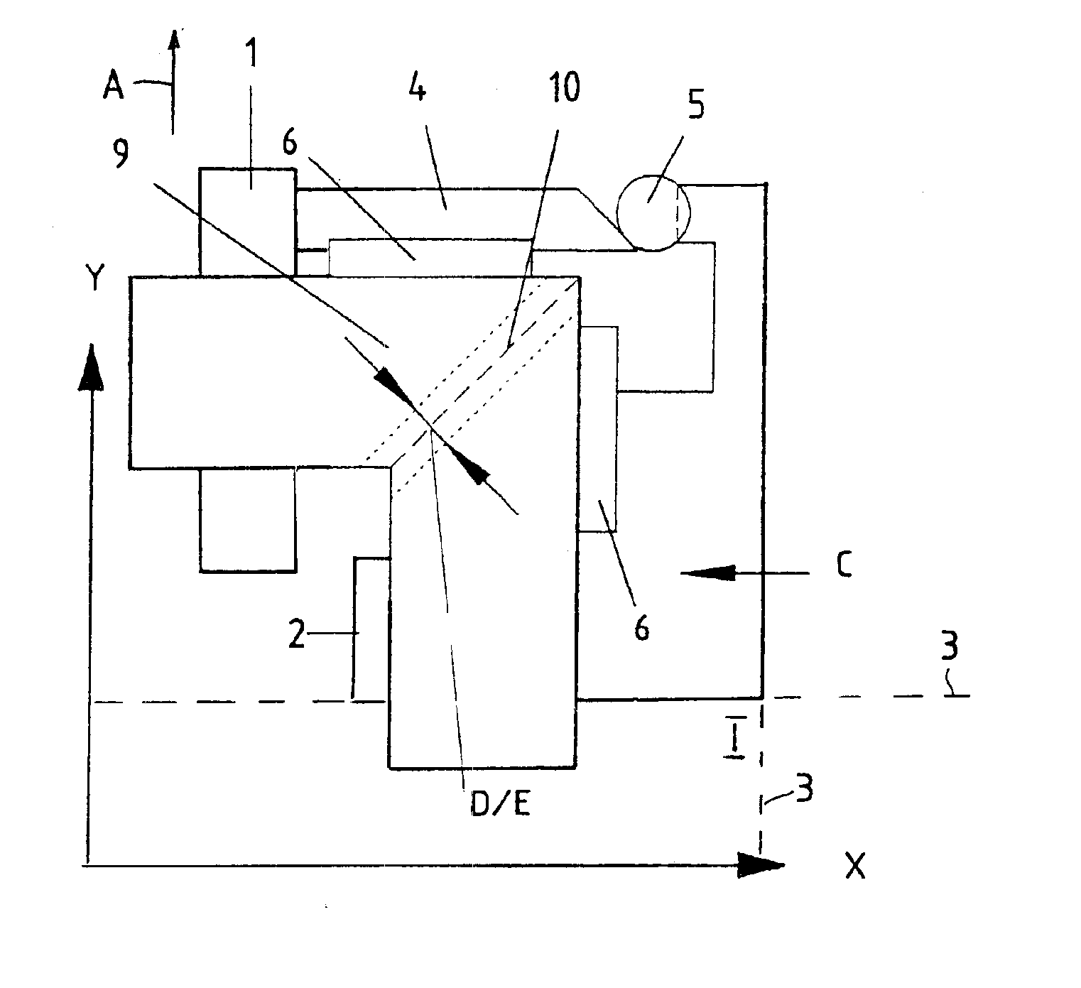
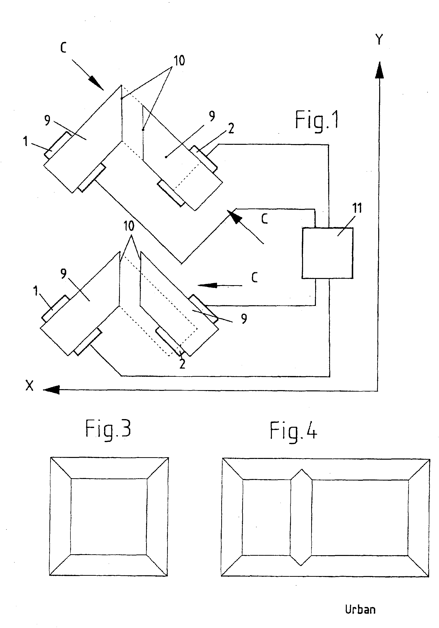
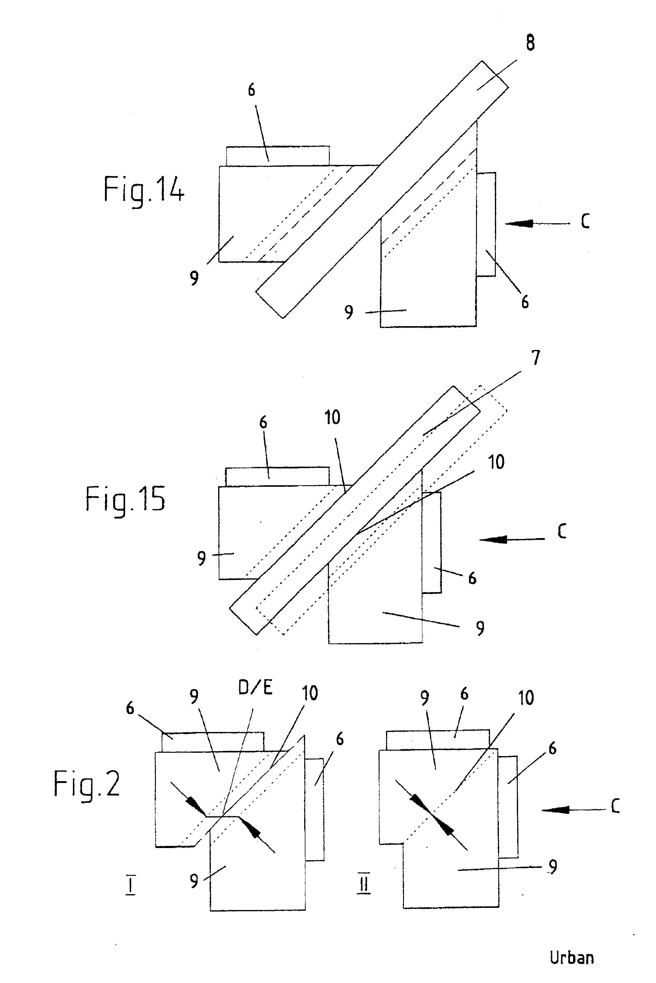
Plastics windows or doors are typically welded by plastics welding machines that are currently substantially made in two different types of construction. Here, it is known to make a corner connection between two plastics profiles with a miter cut by connecting them to one another at the miter cuts, with the plastics profiles that are to be connected being mounted movably and held on carriages and the position of the carriages where appropriate being capable of being fixed. In accordance with the prior art, the plastics profiles are guided through with the two plastics profiles in two different directions of movement with respect to one another.

On the one hand, devices are known that perform, during the joining procedure, a direction of movement, relative to the welding face that is provided by the miter cuts, at an angle of 45°. This is known and is called the diagonal feed process. The disadvantage of this process is that when the partly melted plastics profiles are joined, a relat...


PUM

PropertyMeasurementUnit
Angleaaaaaaaaaa
Angleaaaaaaaaaa

Abstract

A device for welding plastic profiles, including at least two carriages for holding plastic profiles, stoppers for adjustment, stoppers for welding and at least one heating element. The motion of the plastic profiles can be controlled by the device during the welding in such a way that optionally at least two plastic profiles which have to be connected with each other move against each other or one plastic profile stops and the other moves toward it.

Description

FIELD OF THE INVENTIONThe invention relates to a device for welding plastics profiles that are cut into a miter and are welded to one another at a welding face located on the miter cuts, in which the plastics profiles to be connected are mounted and held on moveable carriages, and the position of the carriages may where appropriate be fixed. The invention furthermore relates to a process for making plastics profile frames.BACKGROUND OF THE INVENTIONProfile frames for windows and doors generally comprise, in the simplest form, respectively four profile rods that have to be welded if plastics material is used. Frequently, however, posts or bars are also used to divide them. Profile frames without posts or bars can be welded to one another without difficulty. This would be possible with posts or bars too, but only above a certain size. To weld the profile rods, a range of devices for welding plastics profiles is known. A distinction is made here between single-head, sequential, four-he...

Claims


Application Information

Patent Timeline
IPC IPC(8): B29C65/20B29C65/18
CPCB29C65/20B29C66/1162B29C66/52431B29C66/82261B29C66/843B29C66/52441Y10T156/1744B29L2031/005B29C65/203B29C65/7841
Inventor TESCH, WOLFGANG
Owner URBAN & MASCHENBAU
Why Eureka
Try Eureka