Integrated electrostatic slider fly height control

a slider and height control technology, applied in the direction of maintaining the head carrier alignment, nanoinformatics, instruments, etc., can solve the problems of large temperature rise in the head used in the disc drive, undesired limitation of the electrical performance of the transducer,

Inactive Publication Date: 2005-04-05
SEAGATE TECH LLC
View PDF18 Cites 49 Cited by
  • Summary
  • Abstract
  • Description
  • Claims
  • Application Information

AI Technical Summary

Benefits of technology

The actuator adjusts the fly height spacing as a function of a received actuator electrical input. A feedback circuit provi

Problems solved by technology

In particular, there are large temperature rises in the heads used in a disc drive.
This large fly height at lower temperatures, however, unde

Method used


Image

  • Integrated electrostatic slider fly height control
  • Integrated electrostatic slider fly height control
  • Integrated electrostatic slider fly height control

Examples


Embodiment Construction

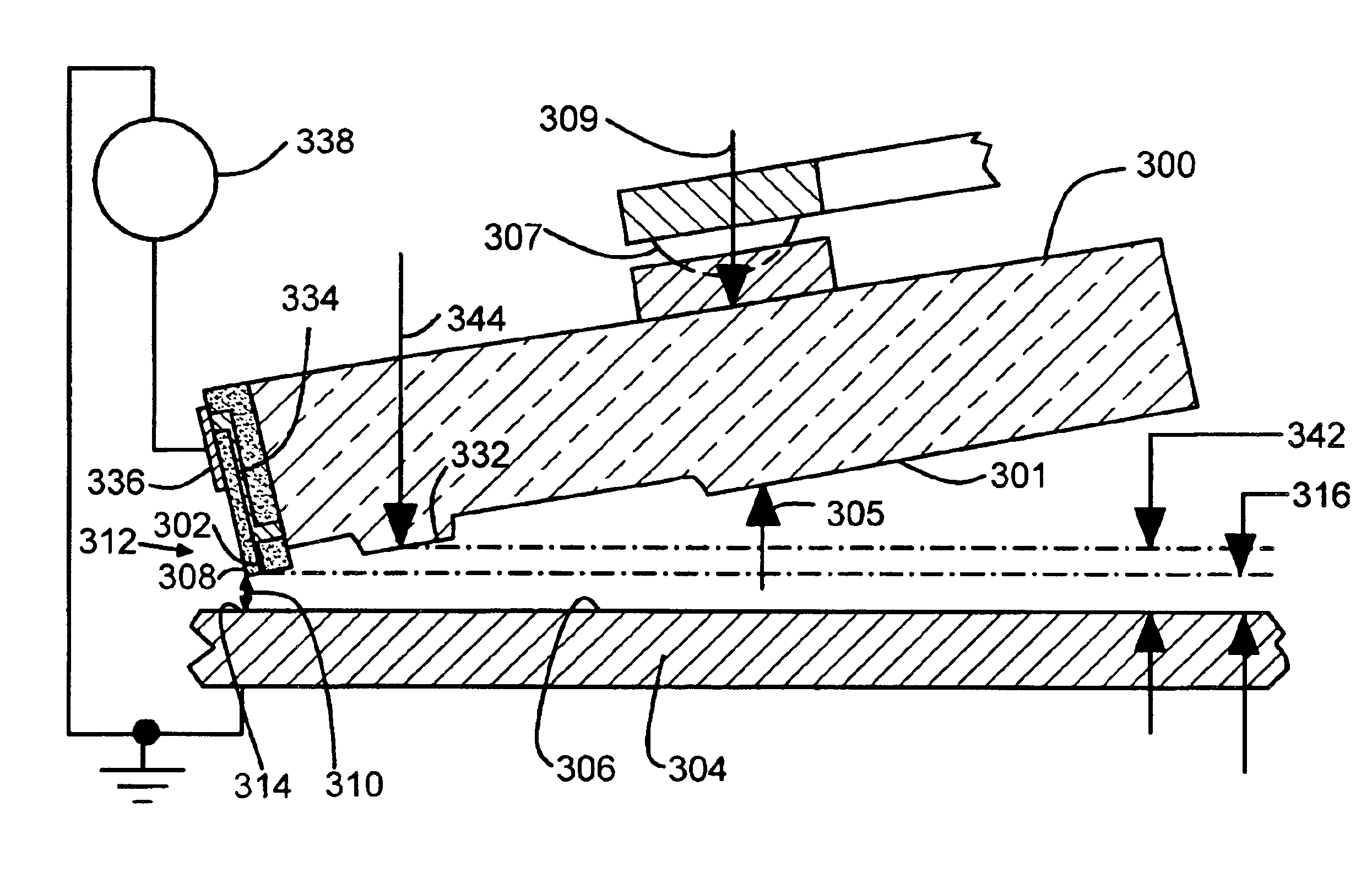
In the embodiments illustrated below, a disc drive includes a slider with a field emission sensor that senses fly height by passing quantum mechanical tunneling current across a gap between the slider and a media surface on a disc. An output from the field emission sensor is fed back to an actuator that adjusts fly height. When the head experiences thermal pole tip protrusion at higher temperatures, then the feedback controls and stabilizes the fly height to avoid head crashes.

As fly heights decrease due to market demand for increasing areal density, the control and stability illustrated by the embodiments becomes increasingly important. Additional factors, such as the desire to use silicon as a slider material to gain processing advantages from the semiconductor industry unfortunately adds further to the fly height control problem by increasing the pole tip protrusion at higher temperatures.

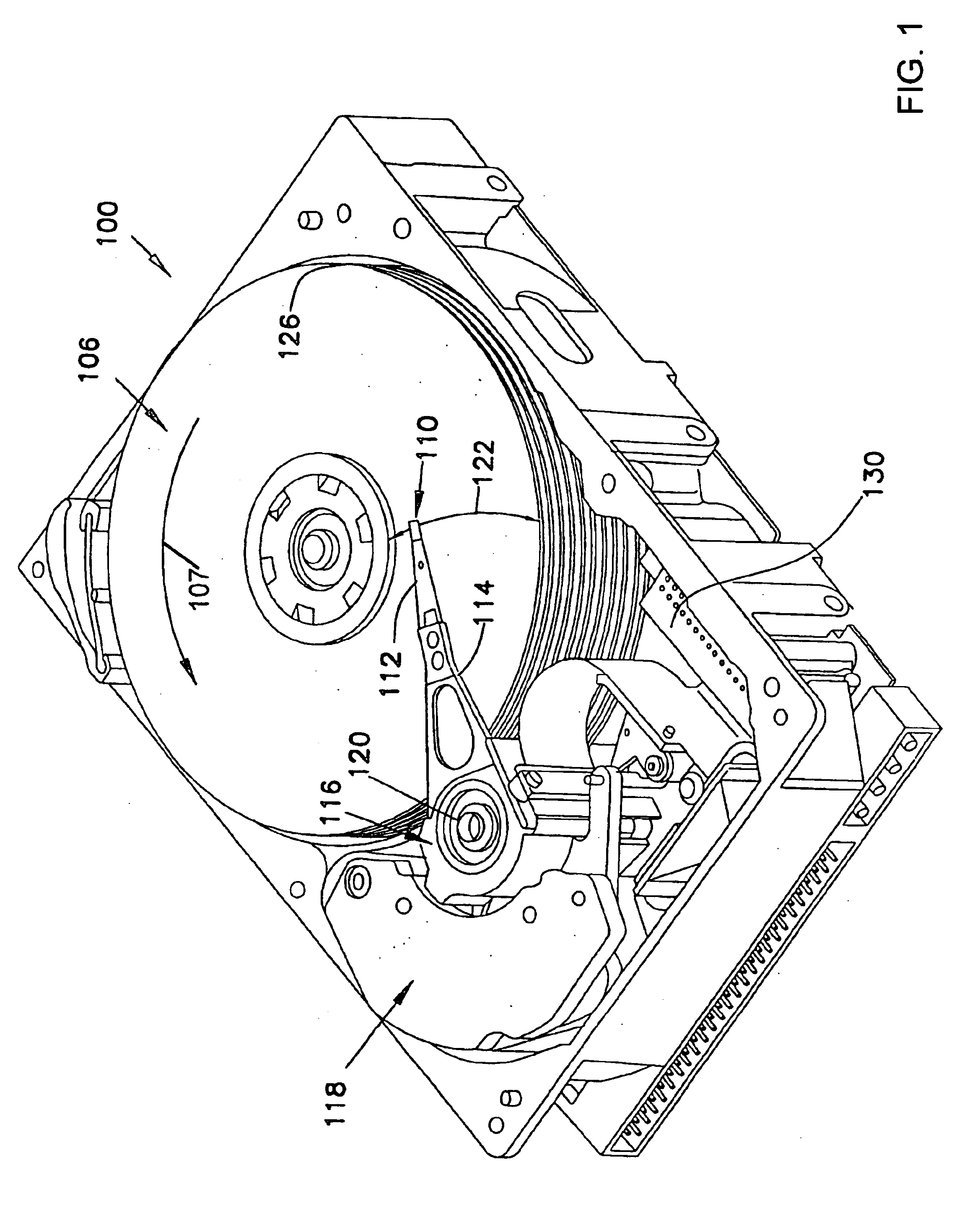
FIG. 1 illustrates an embodiment of a disc drive 100 including a slider 110 that includes on...


PUM


Abstract

A disc drive that includes a slider with a field emission sensor that senses fly height. The sensor has an electrode tip disposed on the slider. The electrode tip faces a media surface across a gap. The sensor conducts a tunneling current through the gap and provides an output representing the length of the gap. An actuator adjusts the fly height spacing. A feedback circuit provides an actuator electrical input as a feedback function of the sensor output to control the fly height spacing.

Description

FIELD OF THE INVENTIONThe present invention relates generally to disc drive data storage devices, and more particularly without limitation to control of fly height spacing between a slider and a disc.BACKGROUND OF THE INVENTIONAfter a disc drive is energized, it warms up and has a temperature rise. In particular, there are large temperature rises in the heads used in a disc drive. The heads include magnetic transducers deposited on slider substrates. The magnetic transducers carry read / write currents that generate heat in the heads. The temperature rise in the heads is large because the heads have a small surface area in relation to the amount of heat that is dissipated in the magnetic transducers.The magnetic transducers have a higher coefficient of thermal expansion (CTE) than the slider substrates. As temperature increases, the magnetic transducers thermally expand at a greater rate than the slider substrates. The thermal expansion causes the pole / shield tips of the magnetic tran...

Claims


Application Information

Patent Timeline
IPC IPC(8): G11B21/21G11B5/60G11B5/58G11B9/00
CPCB82Y10/00G11B5/581G11B21/21G11B5/6005G11B9/1445
Inventor BONIN, WAYNE A.BOUTAGHOU, ZINE-EDDINE
Owner SEAGATE TECH LLC
Why Eureka
Try Eureka