X-ray CT apparatus

a ct apparatus and x-ray technology, applied in the direction of material analysis, tomography, instruments, etc., can solve the problems of large influence of scattered x-rays and shading, difficult merely to increase rotation speed, shorten scan time,

Active Publication Date: 2005-04-05
TOSHIBA MEDICAL SYST CORP
View PDF5 Cites 114 Cited by
  • Summary
  • Abstract
  • Description
  • Claims
  • Application Information

AI Technical Summary

Benefits of technology

One object of the present invention is to ameliorate the above-mentioned problems. To that end, according to one aspect of the present invention, there is provided an X-ray CT apparatus, including: a plurality of X-ray irradiation sources, configured to rotate around an object and to irradiate X-rays to the object; a plurality of X-ray detection units, each of which is positioned opposite each of the plurality of X-ray irradiation sources and configured to detect at least one X-ray

Problems solved by technology

However, since much centrifugal force is applied to rotation portions, such as the X-ray tube and the X-ray detector when a rotation speed is fast, it is technically difficult merely to increase a rotation speed in order to shorten the scan time.
However,

Method used


Image

  • X-ray CT apparatus
  • X-ray CT apparatus
  • X-ray CT apparatus

Examples


first embodiment

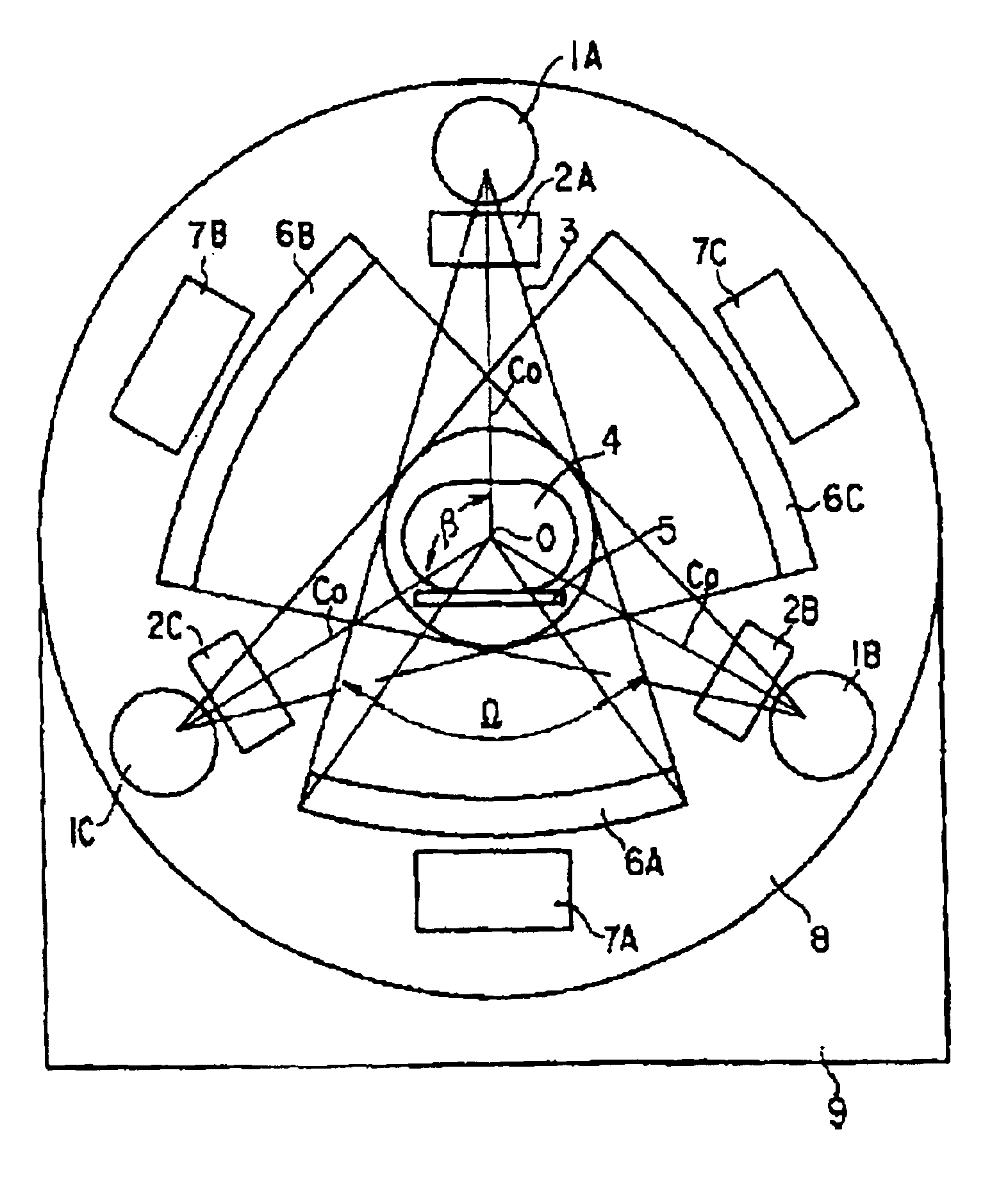
an X-ray CT apparatus is explained with reference to FIG. 3 through FIG. 7. The X-ray CT apparatus includes three X-ray tubes 1A, 1B, and 1C as shown in FIG. 3. The X-ray tubes 1A, 1B, and 1C are arranged at equal intervals on a concentric circle which has a rotation center O. An angle β between center lines Co, each of which travels through each X-ray tube and the rotation center O, is approximately 120 degrees. That is, when the X-ray tube 1A is positioned at 0 degrees, the X-ray tube 1B is positioned at 120 degrees and the X-ray tube 1C is positioned at 240 degrees.

Slits 2A, 2B and 2C are placed at X-ray irradiation window of the X-ray tubes 1A, 1B and 1C, respectively. The slits 2A, 2B, and 2C make fan-shaped X-ray paths 3 that are collimated and have a predetermined thickness. The center line Co is also a center line of the X-ray path 3. A plate on which a patient 4 is situated is positioned such that the patient 4 is on the rotation center O. The X-ray CT apparatus further inc...


PUM


Abstract

An X-ray CT apparatus includes a plurality of X-ray irradiation sources and a plurality of X-ray detection units. Timing of irradiation of X-ray is shifted by each X-ray irradiation source, the detection unit separately obtains projection data and scatter correction data. In a scatter correction unit, scatter correction is performed based on the projection data and the scatter correction data.

Description

CROSS-REFERENCE TO RELATED APPLICATIONSThis application is based upon and claims the benefit of priority from prior Japanese Patent Application No. P2002-288247 filed on Oct. 1, 2002, the entire contents of which are incorporated herein by reference.BACKGROUND OF THE INVENTION1. Field of the InventionThe present invention relates to an X-ray CT apparatus that includes a plurality of X-ray irradiation sources.2. Description of the Related ArtIn an X-ray CT apparatus, an X-ray detector detects a quantity of penetration X-ray irradiated from an X-ray tube, and collects view data based on the X-ray. A tomographic image of a patient is reconstructed based on the collected view data. The view data is a unit of data used for the reconstruction.In a so-called 3rd generation X-ray CT apparatus, when the X-ray tube and the X-ray detector that is positioned opposite the X-ray tube are rotated around the patient 360 degrees, a limited fan-shaped X-ray is irradiated from the X-ray tube to the pa...

Claims


Application Information

Patent Timeline
IPC IPC(8): A61B6/03G01N23/04G01N23/02G06T11/00
CPCA61B6/032A61B6/4014A61B6/5282G06T11/005G01N23/046G01N2223/612A61B6/027G01N2223/419
Inventor OZAKI, MASAHIRO
Owner TOSHIBA MEDICAL SYST CORP
Why Eureka
Try Eureka