Method for applying variable electro-muscle stimulation and system therefor

a technology of electro-muscle stimulation and variable frequency, applied in the field of electro-muscle stimulation (ems), can solve the problems of paralysis of the exercycle pedal by the legs, and achieve the effect of enhancing natural exercise, easy exercise, and encouraging maximum muscle contraction of those muscles

Inactive Publication Date: 2005-04-05
VECTOR INT
View PDF5 Cites 43 Cited by
  • Summary
  • Abstract
  • Description
  • Claims
  • Application Information

AI Technical Summary

Benefits of technology

The purpose of the electro-augmented myociser is to augment and enhance natural exercise by encouraging maximum muscle contraction of those muscles that are easily exercised. It also isolates and enhances contraction of targeted muscle groups that are difficult to exercise. Controls allow the user to establish the level of difficulty that is comfortable and change the level during use. Additionally, the user may change the stimulus to specific sites within a muscle group during use.
The present invention may be incorporated in a vast variety of exercise apparatus including but not limited to equipment used to exercise the abdomen, deltoids, biceps, hamstrings, and quadriceps. It operates under the principle of voltage application being supplied only as the person contracts or actuates his or her muscles. As the person exercises activating a range of motion, the exercise apparatus moves or pivots. The movement or rotation of the equipment is mechanically coupled to a transducer that controls the output of the electrical stimulus. The voltage rises smoothly as the muscle moves causing contraction to peak upon full contraction. In the opposite direction, the voltage reduces ...

Problems solved by technology

This causes pedaling of the...

Method used


Image

  • Method for applying variable electro-muscle stimulation and system therefor
  • Method for applying variable electro-muscle stimulation and system therefor
  • Method for applying variable electro-muscle stimulation and system therefor

Examples


Embodiment Construction

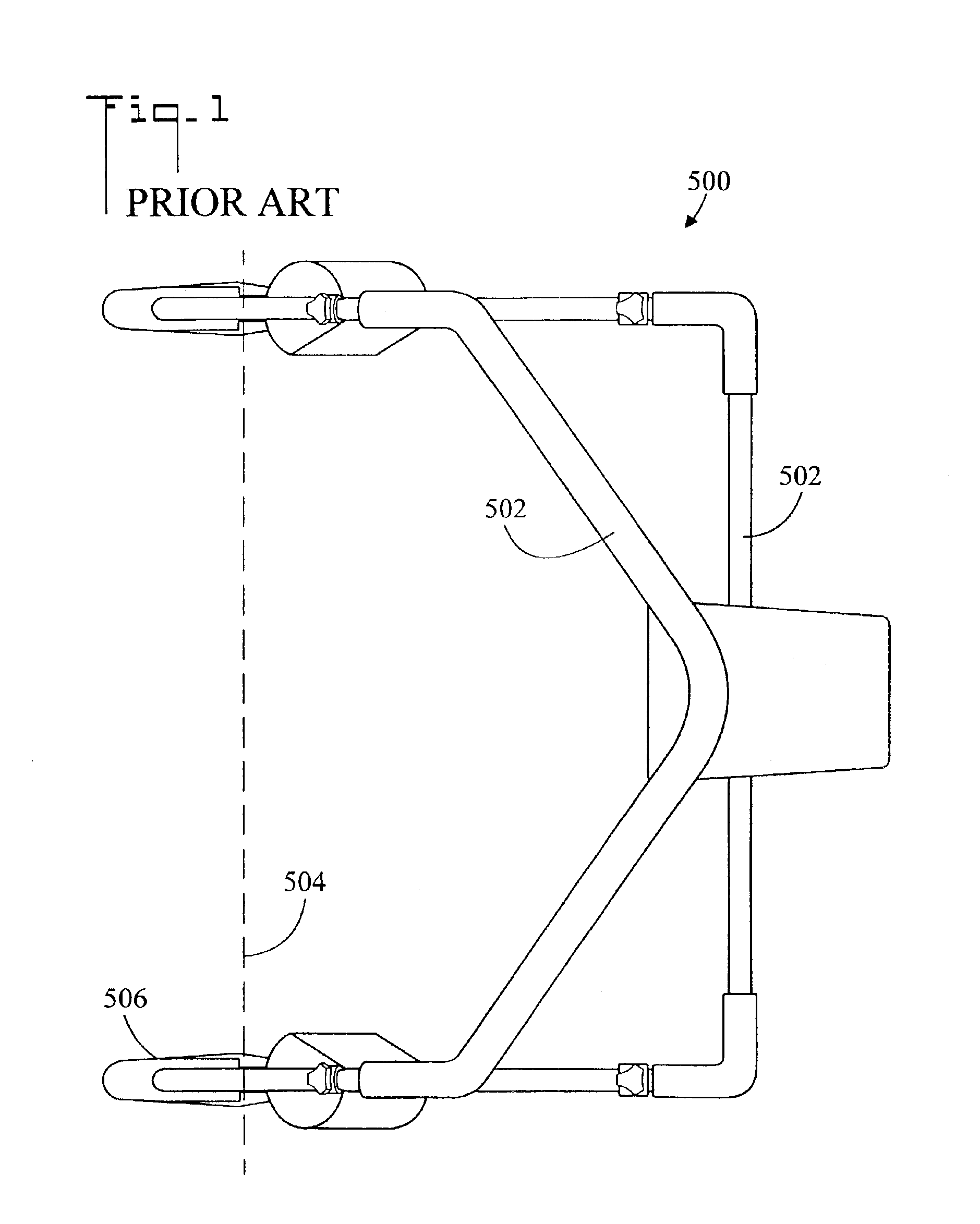
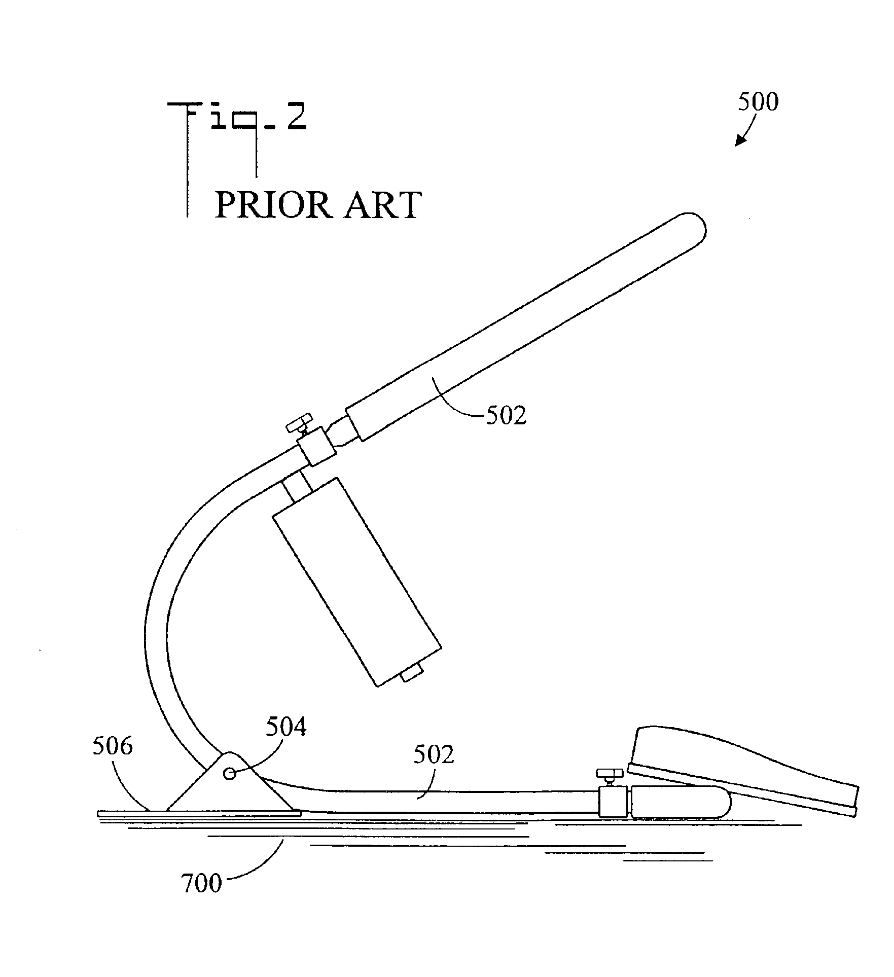
FIGS. 1 and 2 are top plan and side elevation views, respectively, of a prior art exercise apparatus, generally designated as 500. In the shown embodiment, exercise apparatus 500 comprises an abdominal roller which is used to exercise the abdominal muscles of an exercising user. Exercise apparatus 500 includes a member 502 which is rotatable about an axis 504 such as an axle by the exercising user. Member 502 rotates about base 506 which resides on a support surface 700.

FIG. 3 is a side elevation view of prior art exercise apparatus 500 rotated through an angle θ to a second position.

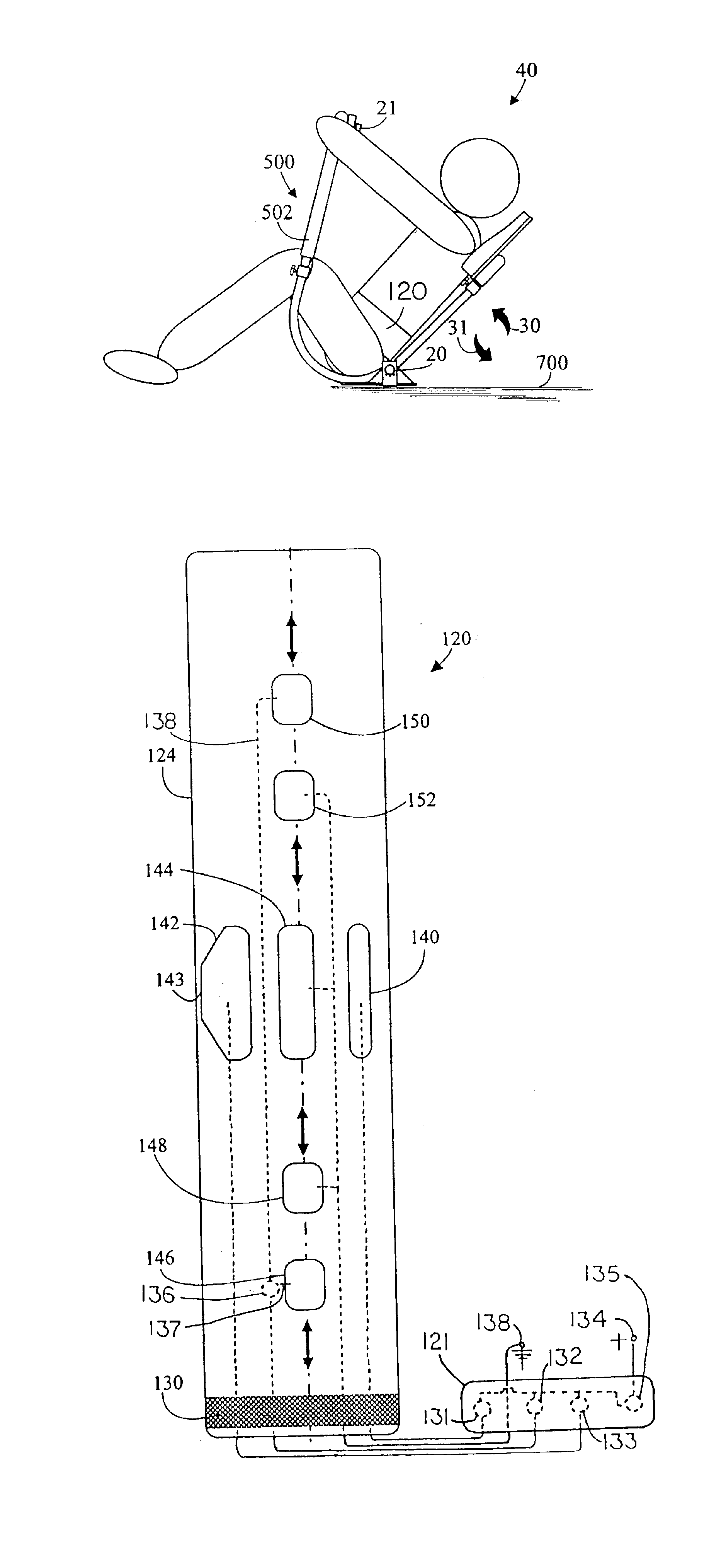
FIGS. 4 and 5 illustrate top plan and side elevation views, respectively, of a system for applying variable electro-muscle stimulation in accordance with the present invention, generally designated as 40. System 40 includes exercise apparatus 500 having a member 502 which is rotated about an axis 504 by an exercising user. A transducer 20 communicates with axis 504, so that as member 502 is rotated abou...


PUM


Abstract

A method for applying variable electro-muscle stimulation (EMS) to an exercising person includes a belt having a plurality of electrodes placed around the abdomen at the rectus abdominis and obliques. The person then gets into an exercise apparatus which has a rotatable component. Attached to the rotatable component is a transducer that senses the position of the component. An EMS generator is connected to the belt through the transducer. As the user exercises in a first direction, increasing stimulation is applied to the subject muscles. As the user moves the rotatable component in the opposite direction, decreasing stimulation is applied to the user. In an alternative embodiment, the belt has at least one pair of electrodes connected to a common adjustment control so that as the voltage increases to one of the electrodes, it decreases to the other electrode of the pair, and vice versa. A toggle switch makes possible the selection of a particular pair.

Description

TECHNICAL FIELDThe present invention pertains generally to electro-muscle stimulation (EMS), and more particularly to a method and system for applying a varying level of EMS as a user activates an exercise apparatus.BACKGROUND OF THE INVENTIONElectro-muscle stimulation (EMS) is well known in the medical art. This technology utilizes a conductive pad or electrode to externally apply a very weak current to a muscle or group of muscles and thereby cause them to contract. The electrode receives an electric stimulation signal from an external voltage / current source, such as an EMS machine. The stimulation signal can be adjusted in amplitude, polarity, frequency, waveform, etc. EMS is commonly used in physical or occupational therapy to strengthen atrophied muscles or paralyzed limbs. It is also used to exercise muscles that are immobilized for long periods of time as a result of muscular or neurological disorders, or extended periods of bed rest arising from injury, surgery, or illness. ...

Claims


Application Information

Patent Timeline
IPC IPC(8): A61N1/36A61N1/32A61H1/02A63B23/02
CPCA61N1/321A61N1/36003A63B23/0244A63B2213/004A63B23/0211
Inventor HURTADO, ARTHUR F.
Owner VECTOR INT
Why Eureka
Try Eureka