
High performance communication architecture for circuit designs using probabilistic allocation of resources

a communication architecture and probabilistic allocation technology, applied in the field of high-performance architectures for circuit design, can solve the problems of inability to directly apply the research in that context to the disclosed architecture in question, the traffic scheduling algorithm can afford to be more complex, and the cost of hardware implementation can be tolerated

Inactive Publication Date: 2005-04-05
NEC CORP
View PDF6 Cites 30 Cited by
  • Summary
  • Abstract
  • Description
  • Claims
  • Application Information

AI Technical Summary

Benefits of technology

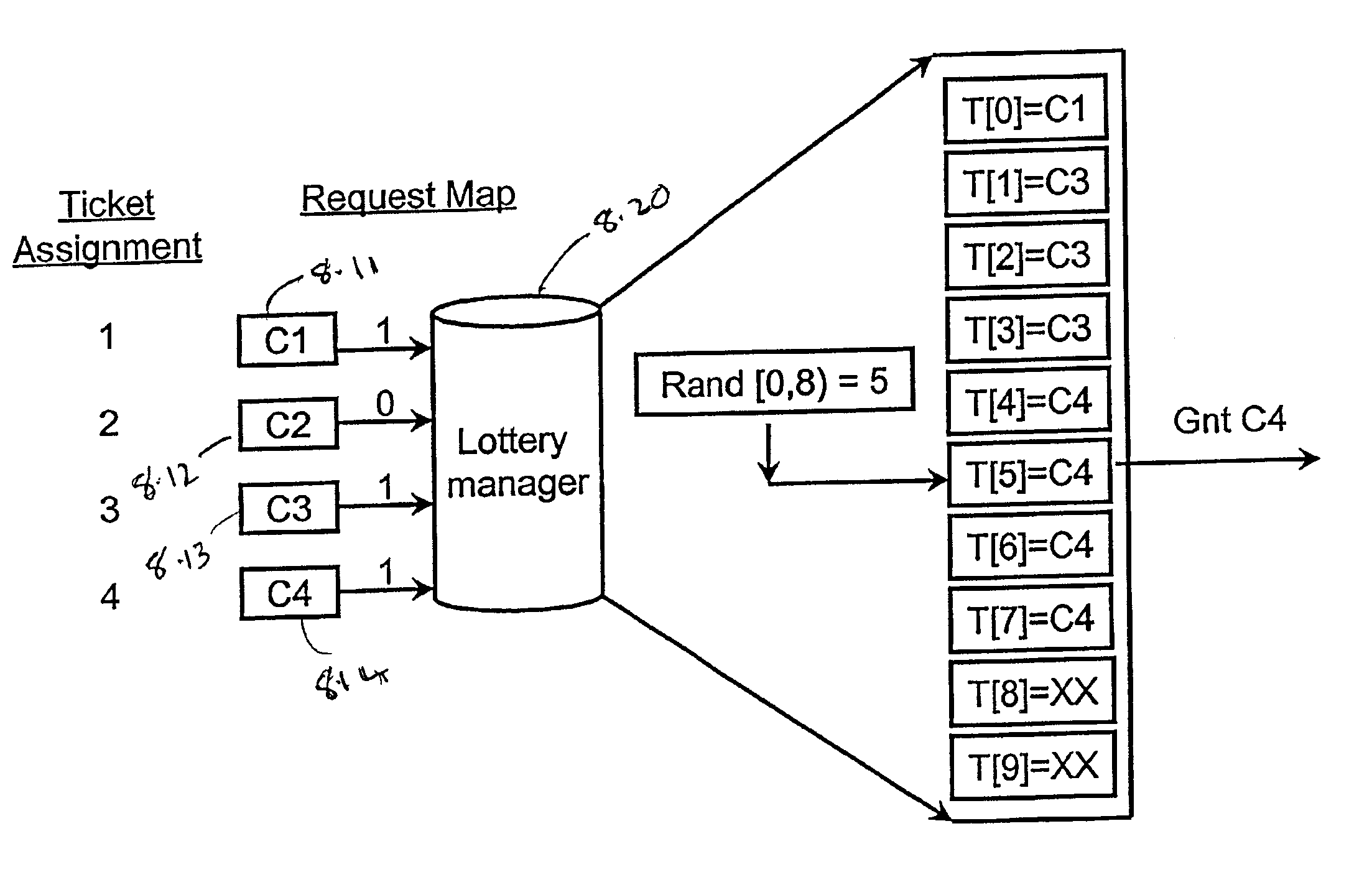
In a further refinement operations of the lottery manager are pipelined with actual data transfers to minimize idle bus cycles.

Problems solved by technology

While the disclosed techniques have some relationship to work on packet switch architectures for large scale networks, previous research in that context cannot be directly applied to disclosed architectures in question, including system-on-chip design context at least due to the following reasons.
Traffic scheduling algorithms need to take care of several issues at the same time, many of which may not be relevant for an application specific system-on-chip.
Traffic scheduling algorithms can afford to be more complex, since the time available to make a scheduling decision is a cell time, as opposed to a bus cycle as in the case of on-chip communication; and hence, higher hardware implementation costs can be tolerated.
However, in that domain, while hardware implementation considerations are irrelevant, the software architecture needs to provide for security and insulation between competing applications.
The problem with TDMA based approaches is that of wasted slots.
The analysis demonstrates that they are each at least incapable of simultaneously providing (i) proportional allocation of communication bandwidth among various components, and (ii) low latency communications for high priority data transfers.

Method used


Image

  • High performance communication architecture for circuit designs using probabilistic allocation of resources
  • High performance communication architecture for circuit designs using probabilistic allocation of resources
  • High performance communication architecture for circuit designs using probabilistic allocation of resources

Examples


example 2

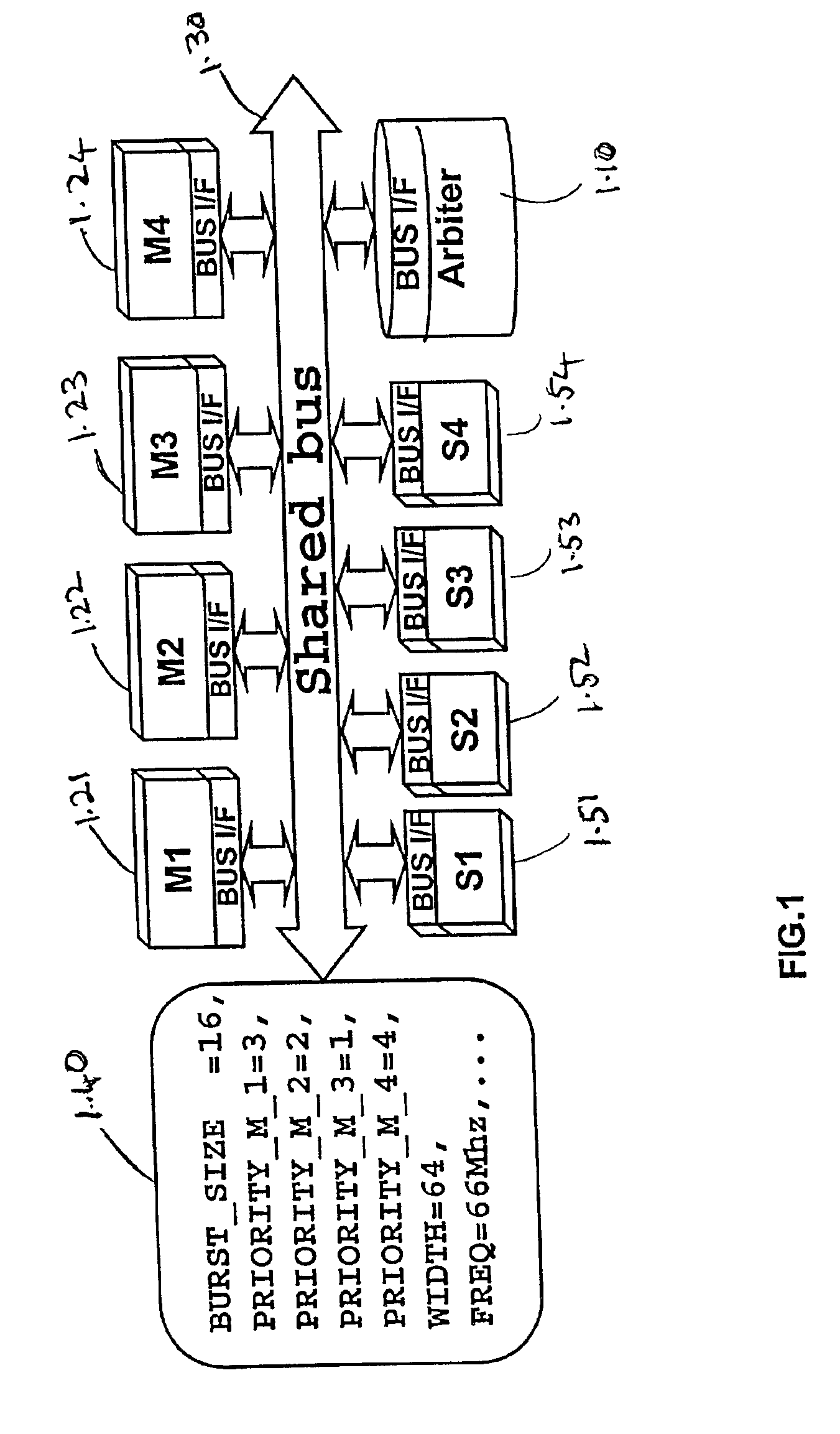
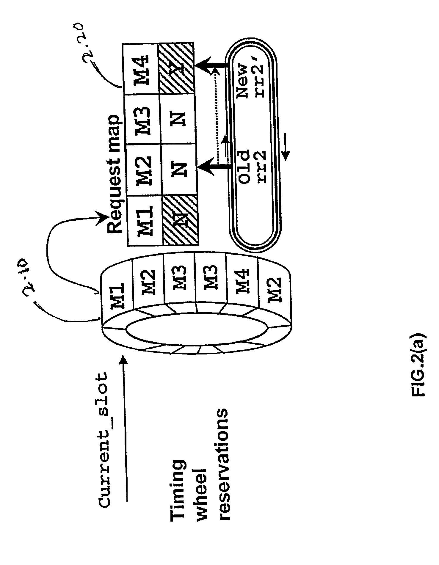
FIG. 4 shows a segment of two execution traces on a TDMA based bus. The system bus has three masters that contend for access. Slots in the timing wheel are reserved in the manner shown in the first row 4.10 of FIG. 4, with 6 contiguous slots defining the burst size of each component. The second row 4.20 and the fourth row 4.40 depict traces that show two different patterns of communication requests generated by the components, each request marked with the associated component's label. The third row 4.30 and fifth row 4.30 depict waveforms that show the actual assignment of masters to bus slots for the given reservations and request traces. From this example, the following observations can be made:Notice that in request Trace1, the requests from a particular component arrive periodically, and very well aligned with the slots reserved for it in the timing wheel. Consequently the time spent by a component in waiting for access to the bus is minimal, in this case only 1 slot.However, un...

example 3

As in Example 1, four components access a single shared bus. In this example also, the relative importance of the communications generated by a component is used to (statically) assign it a “lottery-priority”, which in turn determines its communication latencies and allocated bandwidth fraction. The experiments described in Example 1 are repeated using the LOTTERYBUS architecture instead of the static priority based architecture. FIG. 5 depicts the bandwidth fraction obtained by each component for 24 combinations of lottery-priorities. From this figure, it is observed that the fraction of bandwidth obtained by a component is directly proportional to its lottery-priority. For example, under the first 6 priority combinations, component C1 has the lowest lottery-priority, and receives on the average, 11% of the total bus bandwidth. Between combinations 2134 and 2431, it has lottery-priority equal to 2, and therefore receives approximately double, i.e., 20.8% of the total bus bandwidth....

example 4

Finally, the ability of the LOTTERYBUS architecture to provide low latency communications to high priority burst data transfers is illustrated. The experiments described in Example 2 were repeated for the LOTTERYBUS architecture, and comparative results for an illustrative class of communication traffic are shown in FIG. 6. The histogram compares the average latency of communications by each component (each having different priorities) across the two implementations of the communication architecture. The x-axis denotes the 4 different priority levels assigned to the four components. For each point on the x-axis, the columns compare the average number of bus cycles spent in transferring a single bus word (including time spent in acquiring and using the bus). The communication traffic for this experiment consisted of regular small requests for access to the bus from the lower priority components, and occasional bursty demands from the high priority components. From this figure, it can...


PUM


Abstract

A circuit comprising a plurality of components sharing at least one shared resource, and a lottery manager. The lottery manager is adapted to receive request for ownership for the at least one shared resource from a subset of the plurality of components. Each of the subset of the plurality of components are assigned lottery tickets. The lottery manager is adapted to probabilistically choose one component from the subset of the plurality of components for assigning the at least one shared resource. The probabilistic choosing is weighted based on a number of lottery tickets being assigned to each of the subset of the plurality of components.

Description

I.B. FIELDThis disclosure teaches novel techniques related to high-performance architectures for circuit design. The techniques are illustrated using examples of System on Chip (SoC) designs. It should be clear that, though the disclosed techniques are illustrated using SoC designs, the techniques are equally applicable for any kind of circuit.I.C. BACKGROUND1. IntroductionThe advent of enabling technologies allow integration of entire systems on silicon. This has lead to a proliferation of embedded systems in a variety of application domains that display different design constraints. Example of such design constraints include, but are not limited to, low cost, high performance and low power consumption. There is a simultaneous trend towards shorter system design cycles due to time-to-market pressures, and system customization to meet stringent cost, performance, and power constraints. Because of these demands, it is critical to develop system-level components and architectures that...

Claims


Application Information

Patent Timeline
IPC IPC(8): G06F13/36G06F13/362
CPCG06F13/362
Inventor LAHIRI, KANISHKARAGHUNATHAN, ANANDLAKSHMINRAYANA, GANESH
Owner NEC CORP
Learn More