Storage magazine for propellant charge modules

a technology for propellant charge modules and storage magazines, which is applied in the direction of ammunition loading, ammunition storage, weapons, etc., can solve the problems of difficult and awkward introduction of modules, difficult and difficult to ensure the loading of modules with modules, and achieve easy extraction, easy loading or unloading of modules, and horizontal loading

Inactive Publication Date: 2005-04-12
NEXTER SYST SA
View PDF17 Cites 2 Cited by
  • Summary
  • Abstract
  • Description
  • Claims
  • Application Information

AI Technical Summary

Benefits of technology

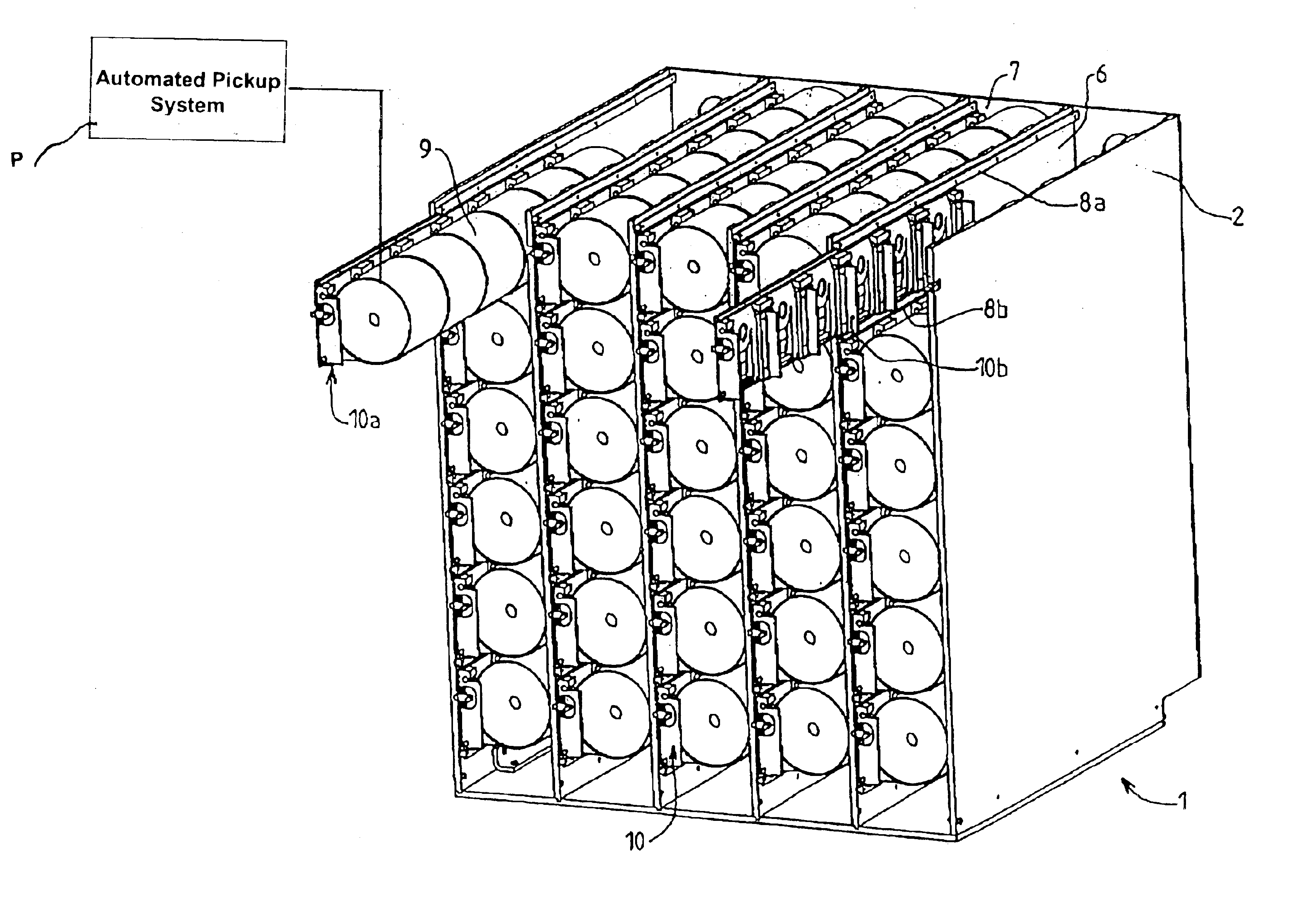
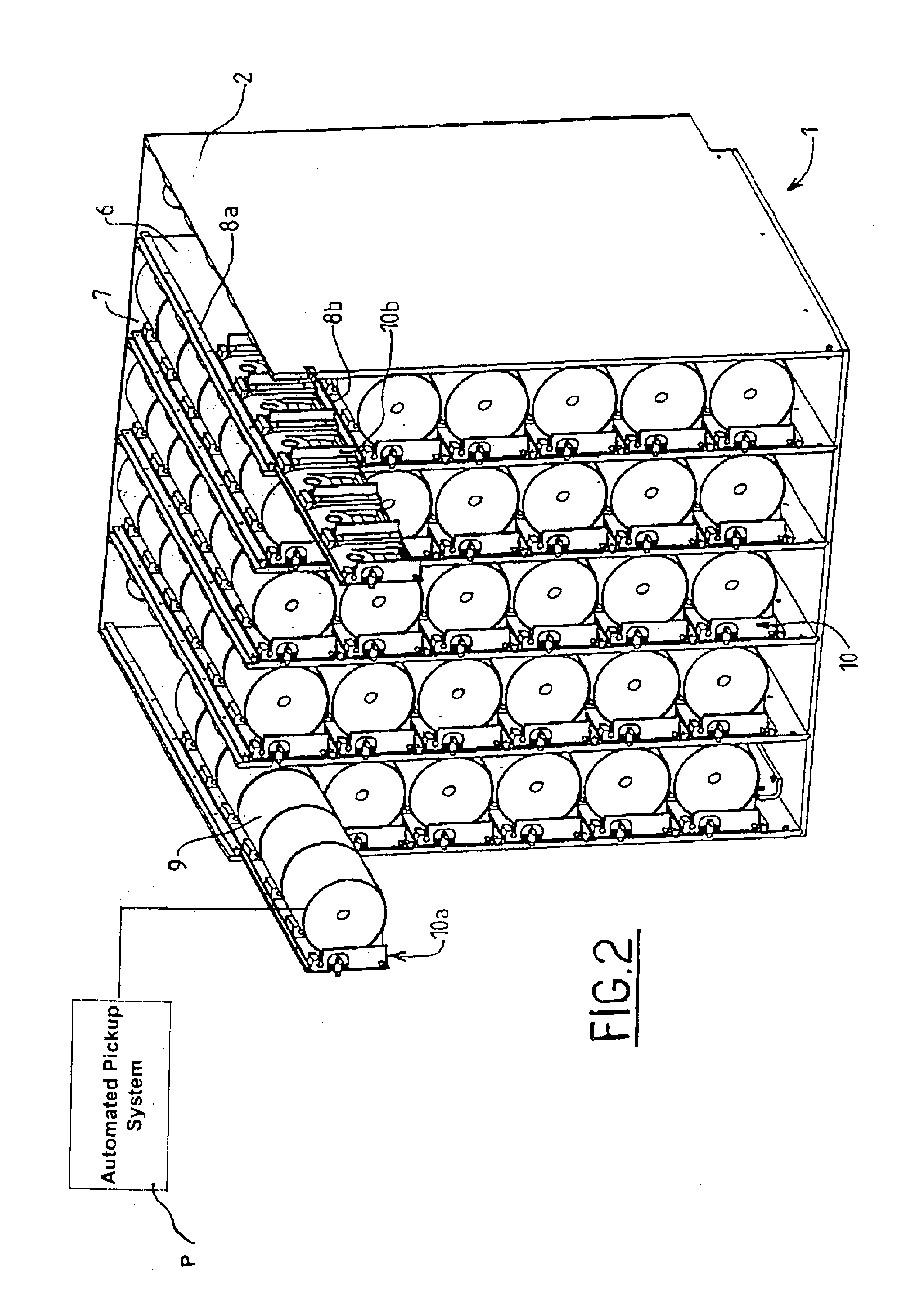
A first advantage of the invention lies in the absence of stresses on the modules that are subjected to neither falls nor friction, which allows the pyrotechnic risk, that is the risk of accidental ignition, to be eliminated.
Another advantage lies in the ease of loading or unloading of the modules since each drawer may be easily extracted making all these operations possible.
Another advantage of the invention lies in the fact that loading is carried out horizontally.
The magazine according to the invention is of simple design and relatively moderate cost.

Problems solved by technology

The main drawback of this magazine lies in the difficulty in ensuring its loading with modules when all or part of the modules have been picked up.
Indeed, these modules can only be introduced into the magazine by the upper part of the magazine in order to be stacked.
It is therefore difficult and awkward to introduce those modules that will be placed at the bottom of the magazine.
Moreover, given that these are pyrotechnic products, any impacts against the bottom or friction between the modules may well cause their ignition.
Lastly, it is also difficult and awkward to renew the modules since there is little available space to access to the inside of this magazine.

Method used


Image

  • Storage magazine for propellant charge modules
  • Storage magazine for propellant charge modules
  • Storage magazine for propellant charge modules

Examples


first embodiment

FIGS. 3 to 5 show a mobile support 10 in the form of a drawer comprising a side flank 12 and catches 13. The side flank is constituted by a substantially plane plate onto which shims 14 and spacers 15 are attached so as to delimit places to receive the modules. In FIG. 3 we can see that each place is limited on either side by a shim 14.

FIG. 4 shows a transverse section of the drawer 10, made at a spacer 15. Each spacer is in the form of a plate attached, for example, by being welded to the flank 12. The catch 13 has a cylindrical profile that matches the shape of the propellant charge module.

FIG. 5 shows a perspective view of the mobile drawer 10, where we see that at both ends the spacer 15a backs onto a single shim 14a whereas each middle spacer 15b is placed between two shims 14b and 14c. Each catch 13 is made integral with a rod 16 by pins (not shown). To make it easier to see in FIG. 5, the rod 16 is fictively extended by dotted lines on the Figure. This rod extends over the fu...

second embodiment

FIGS. 8 and 9 show a drawer 10 of a magazine according to the invention.

This embodiment differs from the previous one in that the shims 14 do not have spacers 15 and in that the reception means do not comprise catches but a support bar 33 integral with arms (34a, 34b, 34c, 34d, 34e, 34f, 34g) that are mounted able to pivot with respect to the shims 14, which are integral with the flank 12 of the drawer.

Each arm 34 is connected to the flank 12 of the drawer by a torque link 35 formed by two hinged connecting rods 30 and 31.

A first connecting rod 30 is mounted able to pivot with respect to the shim 14 and a second connecting rod 31 is mounted able to pivot with respect to the arm 34. The torque link 35 unfolds when the bar 33 is lowered and each arm 34 and its torque link 35 form a side abutment for the propellant charge module (thereby fulfilling the function provided by the spacers 15 in the previous embodiment).

The bar 33, driven by the arms 34, is able to adopt a retracted positio...


PUM


Abstract

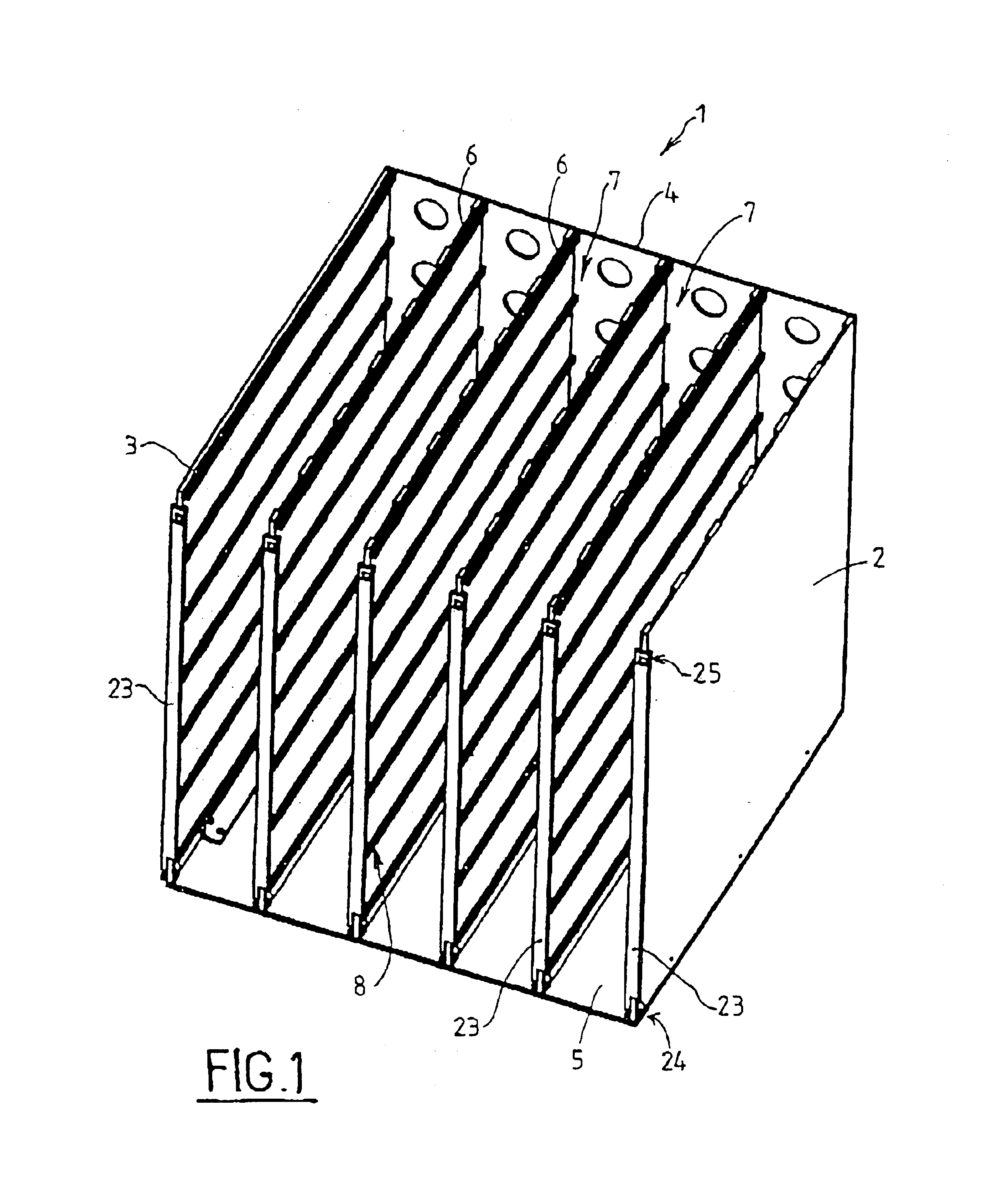
A storage magazine for propellant charge modules for artillery cannons including a set of walls delimiting compartments in which the modules are arranged in superimposed rows, such modules for removal by a pick up system, at least one mobile support for receiving a row of modules, such support in a first extraction position for filling the row and in a second storage position for removing the modules by a pick up system.

Description

FIELD OF THE INVENTIONThe technical scope of the present invention is that of storage magazines for modules constituting propellant charges for artillery cannons.BACKGROUND OF THE INVENTIONAn artillery cannon may be supplied either by ammunition comprising a projectile attached to a stub to form a single assembly or by ammunition comprising a projectile and propellant charge modules. In this last case, the projectile and then the different modules, whose number depends on the distance of the target under fire, must be brought into the gun chamber. The projectiles and the modules are stored in separate magazines and means are provided to bring first the projectile and then the propellant charges following known kinematics so as to be loaded in the gun chamber. These means are commonly designated as automatic pick up system.This system is well known and does not require further explanation here. Reference may be made, for example, to patent FR-2 743 412. This document also describes a...

Claims


Application Information

Patent Timeline
Patent Type & Authority Patents(United States)
IPC IPC(8): F41A9/00F41A9/64
CPCF41A9/64
Inventor MINARD, PATRICKGITTON, PHILIPPECOTTET DUMOULIN, JEAN
Owner NEXTER SYST SA
Why Eureka
Try Eureka