

Method for manufacturing an ink jet recording head, an ink jet recording head manufactured by such method of manufacture, and an ink jet recording apparatus having such ink jet recording head mounted thereon
a technology of ink jet recording head and manufacturing method, which is applied in the field of manufacturing method of ink jet recording head manufactured by such method of manufacture, can solve the problems of defective performance, become an obstacle, become an obstacle, etc., and achieve the effect of filling the filler and good precision
- Summary
- Abstract
- Description
- Claims
- Application Information
AI Technical Summary
Benefits of technology
Problems solved by technology
Method used
Image

Examples
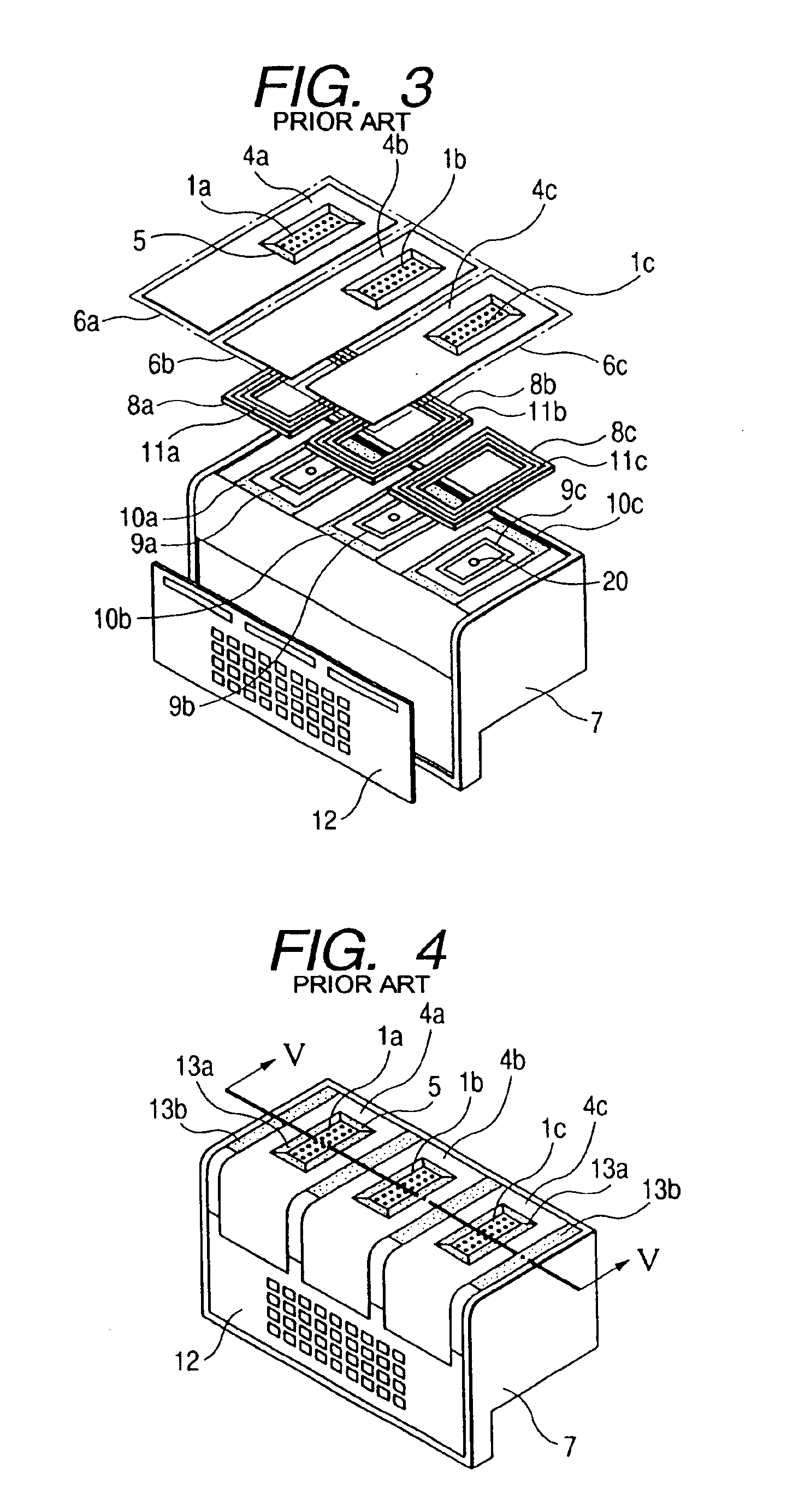
fourth embodiment
erse side and the inner part of the head that represents the structure of the ink jet recording head in accordance with the present invention.
[0064]FIG. 21A is a plan view which shows a part of the laminated state of the elements that constitute the recording element unit represented in accordance with the first embodiment of the present invention; FIG. 21B is a cross-sectional view taken along line 21B—21B in FIG. 21A; and FIG. 21C is a cross-sectional view taken along line 21C—21C in FIG. 21A.
[0065]FIG. 22A is a plan view which shows a part of the filling state of a first filler for the recording element unit represented in accordance with the first embodiment of the present invention; FIG. 22B is a cross-sectional view taken along line 22B—22B in FIG. 22A; and FIG. 22C is a cross-sectional view taken along line 22C—22C in FIG. 22A.
[0066]FIG. 23A is a plan view which shows a part of the state after the first filler has flown, and then, after a second filler is filled and sealed fo...
PUM
| Property | Measurement | Unit |
|---|---|---|
| thick | aaaaa | aaaaa |
| thick | aaaaa | aaaaa |
| thickness | aaaaa | aaaaa |
Abstract
Description
Claims
Application Information