Dental capsule for placement of high viscosity dental composite material with reduce extrusion force

a dental composite material and high viscosity technology, applied in the field of dental capsules, can solve the problems of increasing the risk of dental composite material damage, affecting the physical properties of dental composite materials, and many of the preferred composite materials becoming too viscous for easy dispensing of capsules, etc., and achieve the effect of less likely to be damaged

Inactive Publication Date: 2005-04-12
CENTRIX
View PDF33 Cites 18 Cited by
  • Summary
  • Abstract
  • Description
  • Claims
  • Application Information

AI Technical Summary

Benefits of technology

It is an advantage of the present invention that substantially all of the dental material is extruded.
It is a further advantage of the present invention that the dental material is less likely to be damaged due to the forces of extrusion.
It is a feature of the present invention that different axes are used for the body portion, transition portion and the discharge portion of the capsule.
It is a further feature of the present invention that the capsule has flexible walls in combination with a conical shaped piston.
These and other objects, advantages, and features will become readily apparent in view of the following more detailed description.

Problems solved by technology

However, as the dental composite materials changed and improved, the viscosity and thixotropic nature of the dental composite material created problems in the dispensing thereof in a capsule.
Many of the preferred composite materials became too viscous for easy dispensing with a capsule.
Often, the force required to dispense the high viscosity dental composite materials would make its placement difficult for the dentist, as well as possibly damaging or changing the physical properties of the dental composite material.

Method used


Image

  • Dental capsule for placement of high viscosity dental composite material with reduce extrusion force
  • Dental capsule for placement of high viscosity dental composite material with reduce extrusion force
  • Dental capsule for placement of high viscosity dental composite material with reduce extrusion force

Examples


Embodiment Construction

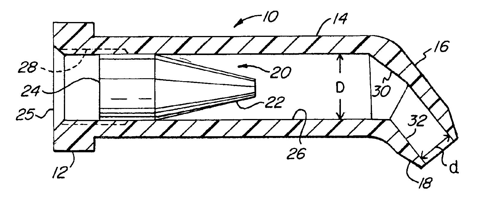
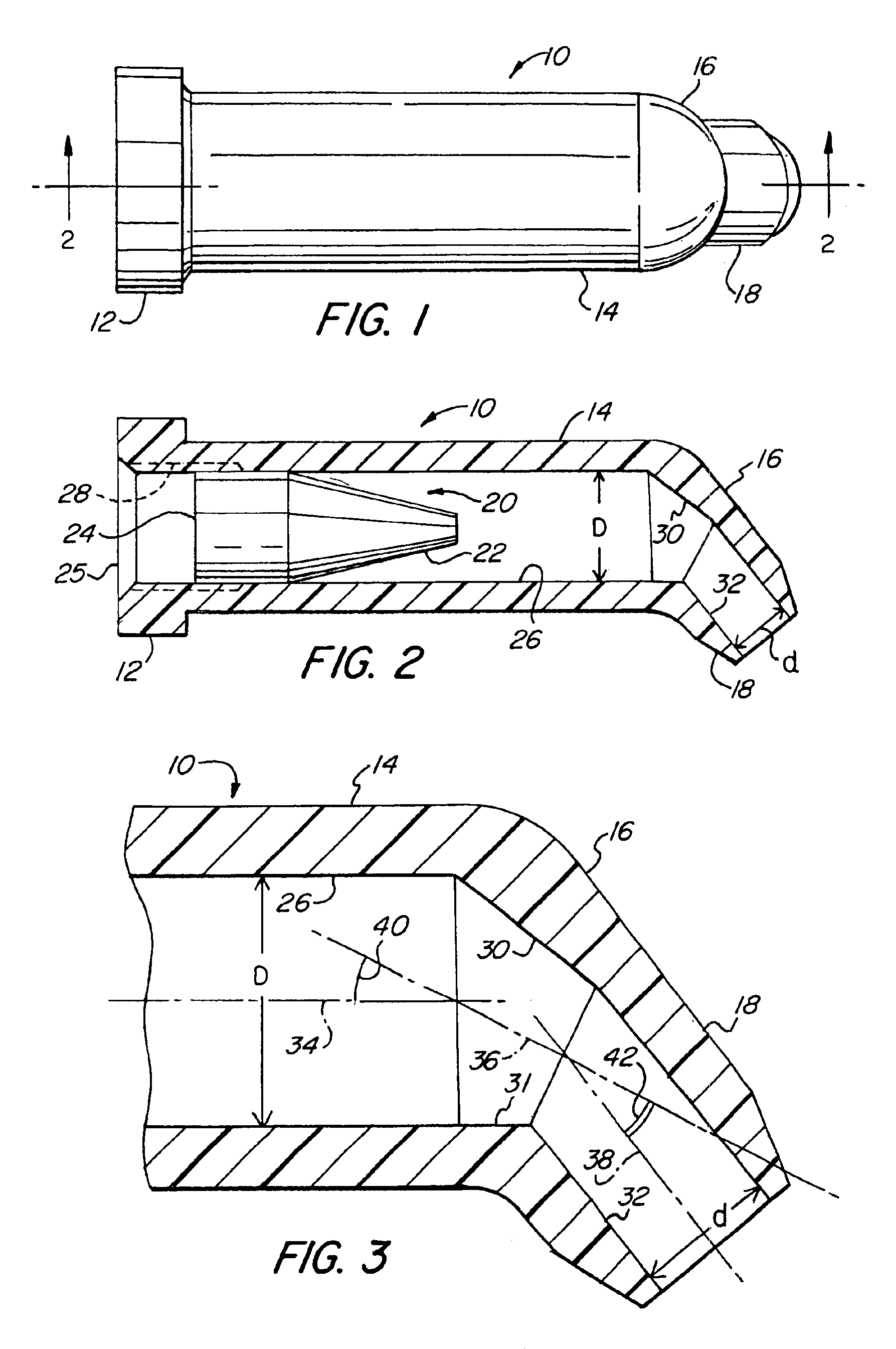
FIG. 1 is a plan view of a dental capsule 10. The dental capsule 10 comprises a flange portion 12, a body portion 14, a transition portion 16, and a discharge portion 18. The capsule 10 may be filled with a high viscosity dental material. The capsule 10 and is dispensed using a syringe which may have a mechanical advantage, such as the syringe disclosed in U.S. Pat. No. 5,489,207 entitled “Dental Cartridge Extruder with Rigid Drop-in Front End” issuing to Dragan et al on Feb. 6, 1996, which is herein incorporated by reference.

FIG. 2 more clearly illustrates the internal configuration of the dental capsule of the present invention. A piston 20 having a flexible conical front portion 22 and a cylindrical rear portion 24 is placed within the inside diameter 26 of the body 14 of the cartridge 10. The inside diameter 26 has a diameter D. At the rear of the body portion 14 is opening 25. The piston 20 is placed within the opening 25. Material may be predosed within the body 14. A vent 28 ...


PUM


Abstract

A dental capsule for extruding high viscosity dental material providing reduced extrusion force. The dental capsule comprises a body portion, a transition portion and a discharge portion. The transition portion has an axis having an angular relationship with the axis of the body portion and the axis of the discharge portion. This relationship and transitional portion reduces the extrusion force required in extruding high viscosity dental material. In another embodiment of the present invention, a flexible piston having a conical front end is utilized to more fully extrude the dental material from the dental capsule. The dental capsule may have flexible walls with the flexible piston and walls cooperating to extrude substantially all of the dental material. The present invention, when used with high viscosity dental materials, results in less extrusion force required and does not damage the dental material during extrusion.

Description

FIELD OF THE INVENTIONThe present invention relates generally to a dental capsule used in the placement of a high viscosity composite restorative dental material, and more specifically to a unit dose dental capsule having an internal configuration and a piston that provides a reduced force for extruding the high viscosity dental material.BACKGROUND OF THE INVENTIONDental composites have been used for many years for restoring teeth. Initially, restorative materials were placed in a cavity of a tooth with a spatula or other packing dental instrument. It became desirable to dispense the composite materials with a capsule and syringe for ease of dispensing and to avoid air bubbles or voids from forming, as often occurred with the spatula packing techniques. However, as the dental composite materials changed and improved, the viscosity and thixotropic nature of the dental composite material created problems in the dispensing thereof in a capsule. Many of the preferred composite materials...

Claims


Application Information

Patent Timeline
Patent Type & Authority Patents(United States)
IPC IPC(8): A61C5/06A61C5/00A61J1/06A61C5/04
CPCA61C5/066A61C5/66
Inventor DRAGAN, WILLIAM B.ROWE, GORDON
Owner CENTRIX
Why Eureka
Try Eureka