Implantable device for injecting medical substances

a technology for injecting devices and medical substances, which is applied in the direction of medical devices, other medical devices, etc., can solve the problems of not always being able to accurately locate the surface of the membrane, and achieve the effects of facilitating the injection operation, reducing leakage risk, and simple design

Inactive Publication Date: 2005-04-12
CIE EURO D'ETUDES & DE RECH DE DISPOSITIFS POUR L'IMPLANTATION PAR LAPAROSCOPIE
View PDF10 Cites 119 Cited by
  • Summary
  • Abstract
  • Description
  • Claims
  • Application Information

AI Technical Summary

Benefits of technology

Consequently, the object of the invention is to propose a novel device for injecting medical substances that makes it possible to remedy the various drawbacks set out above, by providing a device which is not traumatic while eliminating any risk of leakage or of the membrane becoming separated, the device being simple in design and facilitating the injection operation in general.
Another object of the invention is to propose a novel injection device which facilitates insertion of the needle into the chamber of the housing so as to ensure that the user of the needle does not need to puncture the skin of the patient several times in order to locate the membrane. It is not always possible to locate the surface of the membrane accurately merely by palpating the skin of the patient. Thus, the proposed device makes it possible to reach the chamber in complete safety, even if the needle is inserted at an angle through the thickness of the membrane.
Another object of the invention is to propose a novel injection device which is easy to immobilize within the body of the patient.
the side walls and the distal wall of the rigid body being non-pierceable by the needle so as to prevent the needle penetrating into the body of the patient while it is being inserted into the chamber;

Problems solved by technology

It is not always possible to locate the surface of the membrane accurately merely by palpating the skin of the patient.

Method used


Image

  • Implantable device for injecting medical substances
  • Implantable device for injecting medical substances
  • Implantable device for injecting medical substances

Examples


first embodiment

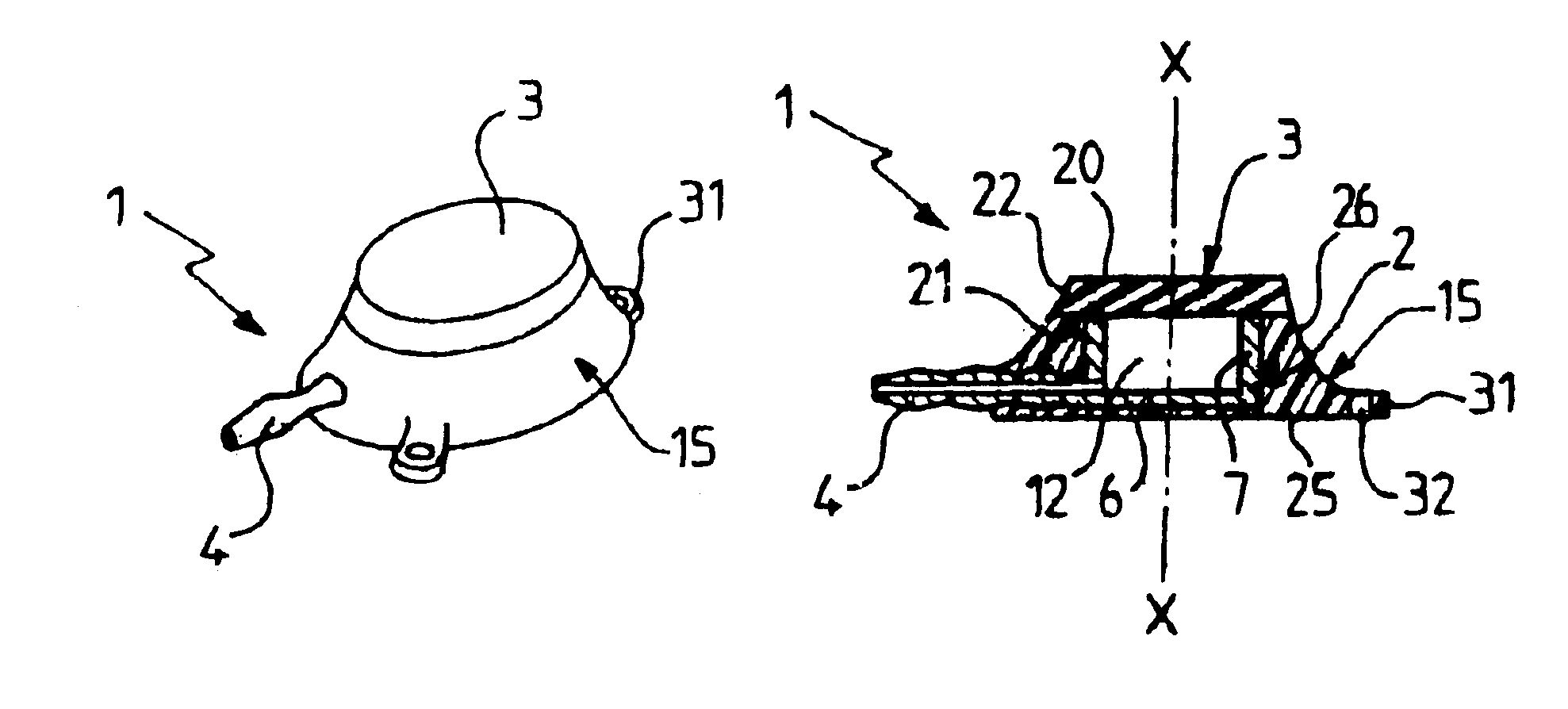
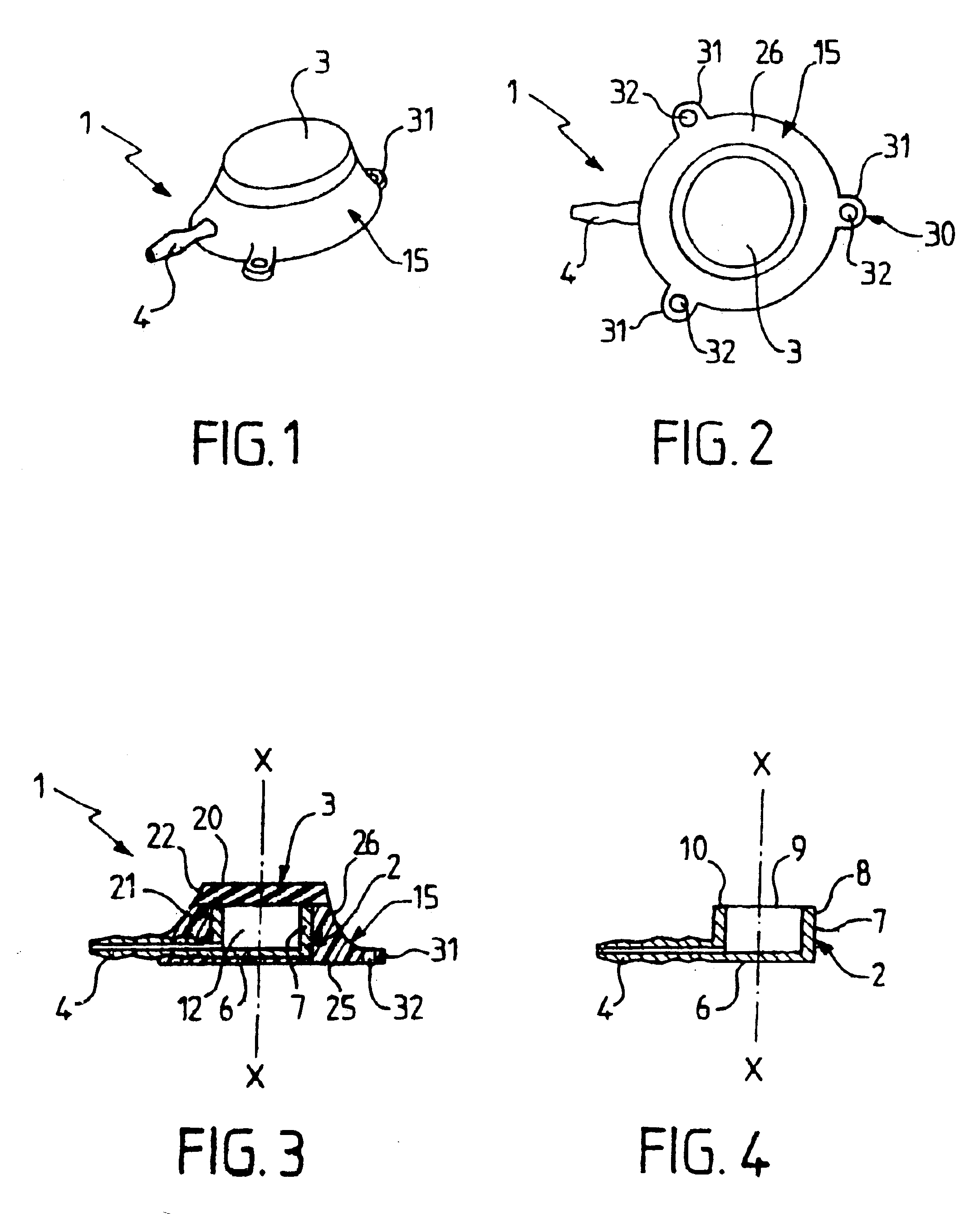
In order to anchor the device 1 securely inside the patient's body, the base 25 of the casing 15 possesses retention means 30 which, in a first embodiment, are implemented in the form of three lugs 31 projecting from the outline of the base 25. Orifices 32 are formed through the lugs 31. The three lugs 31 are uniformly distributed around the base 25, and are thus mutually spaced apart at 120° intervals.

In a variant, the device 1 is provided with a single lug 31.

second embodiment

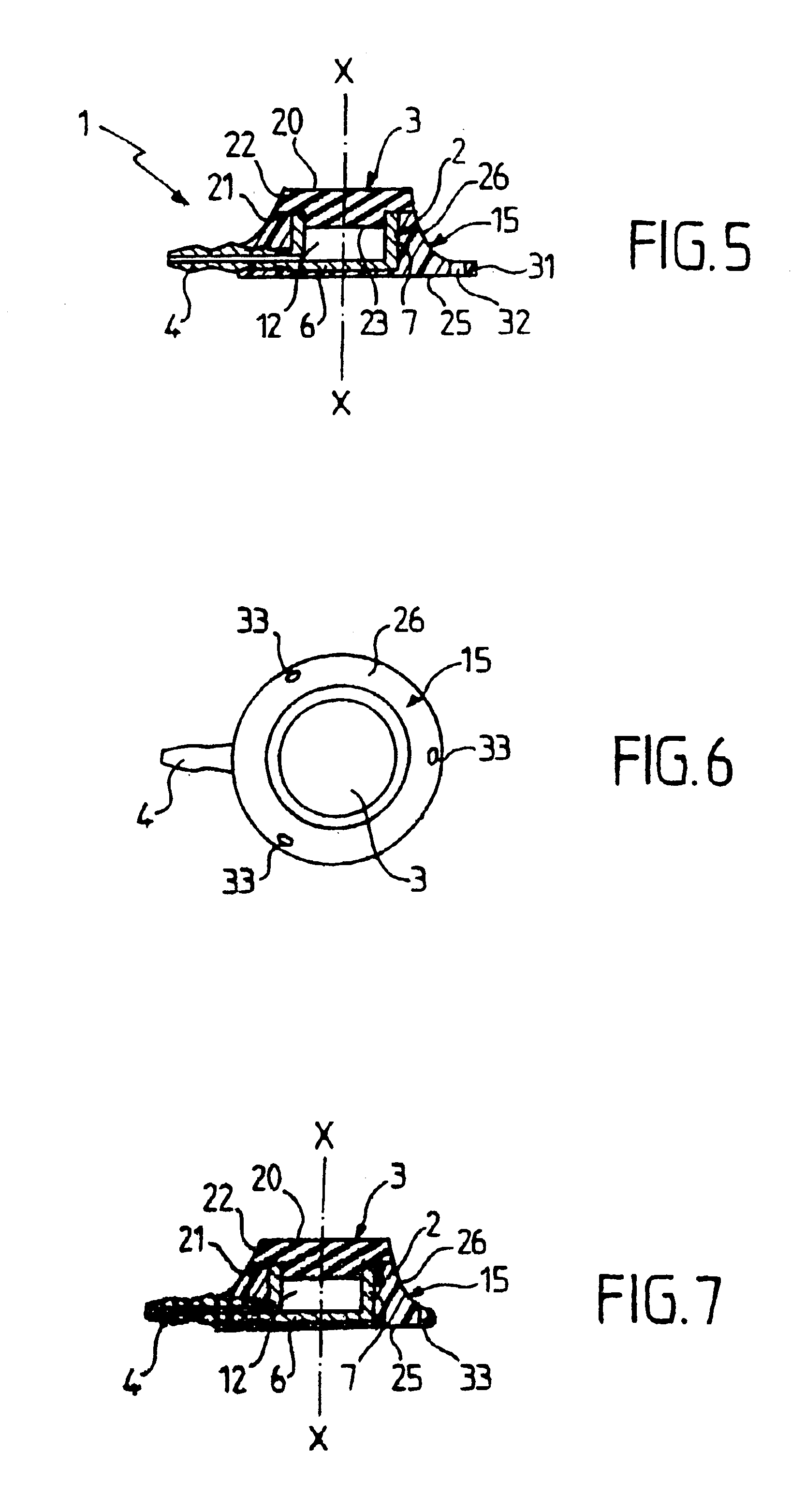
The second embodiment as shown in FIG. 5 differs from the first embodiment as described above solely by the thickness of the membrane 3 which in this case is of varying thickness.

The thickness of the membrane 3 in register with the opening 9 of the housing 2 is greater than the thickness of the remainder of the membrane so as to anchor the membrane securely in a transverse direction within the housing 2. The membrane 3 thus comprises a central body 23 which penetrates a short distance into the opening of the housing 2 and co-operating with the remainder of the membrane to form a shoulder. This avoids excessive lateral movement of the membrane 3 while the nurse is palpating the patient's body to locate the device 1 under the patient's skin in order to insert the needle.

third embodiment

In the third embodiment shown in FIGS. 6 and 7, the retention means 30 of the device 1 are in the form of three orifices 33 which are formed directly through the thickness of the periphery of the base 25.

In this third embodiment, the cross-section of the periphery of the base 25 is rounded so as to be non-traumatic.

Advantageously, the diameter of the base 25 is enlarged to a lesser extent than in the first and second embodiments in order to minimize the risk of leaving any residue of silicone inside the body when the device 1 is removed from the patient.

In yet another variant, an internal chamfer (not shown) is provided on the ring 10 as defined by the free ends 8 of the side walls 7 of the housing 2 so as to make it easier for the needle to penetrate into the chamber 12 when the needle is pushed in from the side, through the side walls 22 of the membrane 3.

The device of the present invention thus possesses a casing 15 which is integral with the membrane 3 and which is of varying fl...


PUM


Abstract

An injection device (1) for injecting medical substances and designed to be implanted in a subcutaneous zone of the body of a patient. The device includes a hollow rigid housing (2) having an opening which is closed hermetically by a membrane (3) so as to define a chamber (12). A duct (4) is connected to the housing to connect the chamber to the outside of the device. The device also has a casing (15) of elastomer material which covers the housing, and the membrane forms an integral portion of the casing. The implantable device is suitable for performing chemotherapy treatment.

Description

TECHNICAL FIELDThe present invention relates to the technical field of devices for injecting medical substances, which devices are designed to be implanted in a subcutaneous zone of the body of a patient in order to inject said substances into the body of the patient.Such injection devices are also referred to implantable sites.The present invention relates to an injection device of the type comprising a hollow rigid housing having a distal wall from which there extend side walls whose free ends define a proximal opening, a membrane which is situated over the free ends of the side walls in order to close the proximal opening in substantially hermetic manner, thereby defining a chamber, and a duct connected to the rigid housing and which connects the chamber to the outside of the injection device.PRIOR ARTDuring injection, the membrane which is accessible through the skin of the patient is designed to be pierced by a needle so as to deliver a dose of medical substance into the body o...

Claims


Application Information

Patent Timeline
Patent Type & Authority Patents(United States)
IPC IPC(8): A61M39/02A61M37/00
CPCA61M39/0208A61M2039/0226
Inventor BENCHETRIT, SALOMON
Owner CIE EURO D'ETUDES & DE RECH DE DISPOSITIFS POUR L'IMPLANTATION PAR LAPAROSCOPIE
Why Eureka
Try Eureka