Call receiving system apparatus and method having a dedicated switch

a call receiving system and switch technology, applied in the field of dedicated switch call receiving pager apparatus, system and method, can solve the problem of not being able to commit further fraud, and achieve the effect of reducing the amount of fraud associated

Inactive Publication Date: 2005-04-12
LBT IP LLC
View PDF33 Cites 66 Cited by
  • Summary
  • Abstract
  • Description
  • Claims
  • Application Information

AI Technical Summary

Benefits of technology

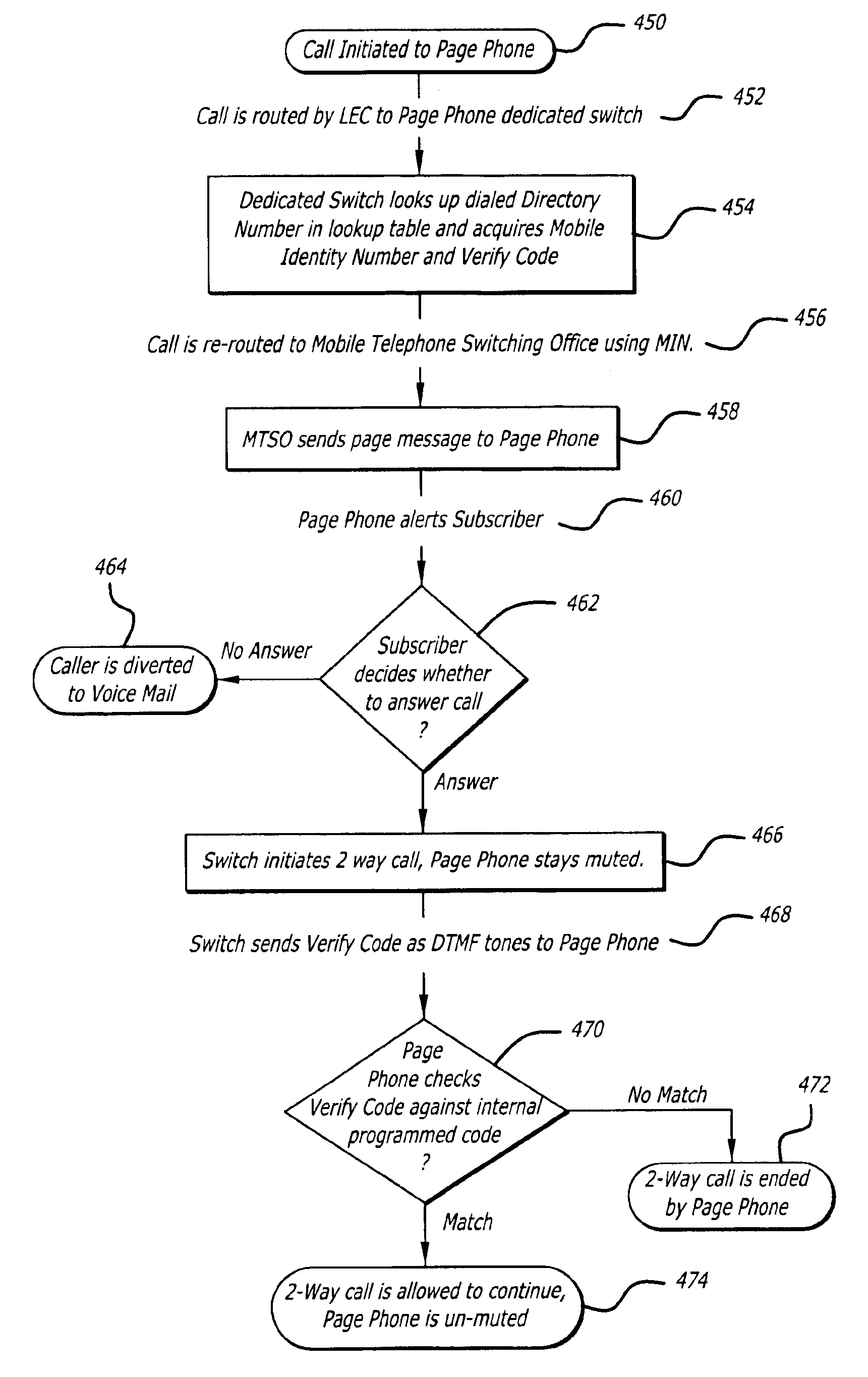
It is still another object of the present invention to provide a call receiving pager apparatus, system and method utilizing a dedicated switch wherein the dedicated switch is used to provide proprietary access, billing functions and other enhanced features including, but not limited to, calling party pays billing, selective drop in messaging, voicemail service and verification coding.
It is still another object of the present invention to provide a system and method for reducing fraud associated with the personal communications system.

Problems solved by technology

Although combined radiotelephone and paging systems have been described, none of those systems prevents initiation of a direct two-way wireless communication by the subscriber or holder of the dual paging / radiotelephone system, nor do any of those combined systems described above include a system wherein only the outside calling party pays for the telecommunication when the caller and subscriber are activated.
Such an apparatus, system and method will prevent the accumulation of billings associated with frivolous or unnecessary calls made by children in that the apparatus, system and method do not allow those possessing the apparatus to make direct outgoing calls.
Further, if the apparatus were stolen, it would be impossible to commit further fraud by charging the subscriber of the apparatus for calls because the apparatus, system and method employ caller generated billing.

Method used


Image

  • Call receiving system apparatus and method having a dedicated switch
  • Call receiving system apparatus and method having a dedicated switch
  • Call receiving system apparatus and method having a dedicated switch

Examples


Embodiment Construction

The present invention may be described herein in terms of functional block components and various processing steps. It should be appreciated that such functional blocks may be realized by any number of hardware components configured to perform the specified functions. For example, the present invention may employ various integrated circuit components, e.g., memory elements, digital signal processing elements, logic elements, look-up tables, and the like, which may carry out a variety of functions under the control of one or more microprocessors or other control devices. In addition, those skilled in the art will appreciate that the present invention may be practiced in conjunction with any number of data transmission protocols and that the systems, methods, and apparatus described herein are merely exemplary applications for the invention. Further, it should be noted that the present invention may employ any number of conventional techniques for data transmission, signaling, data pr...


PUM


Abstract

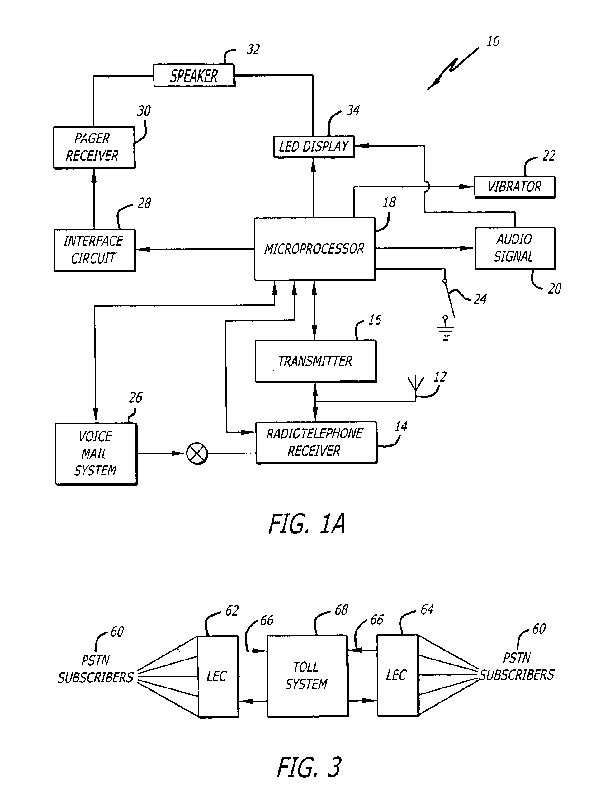
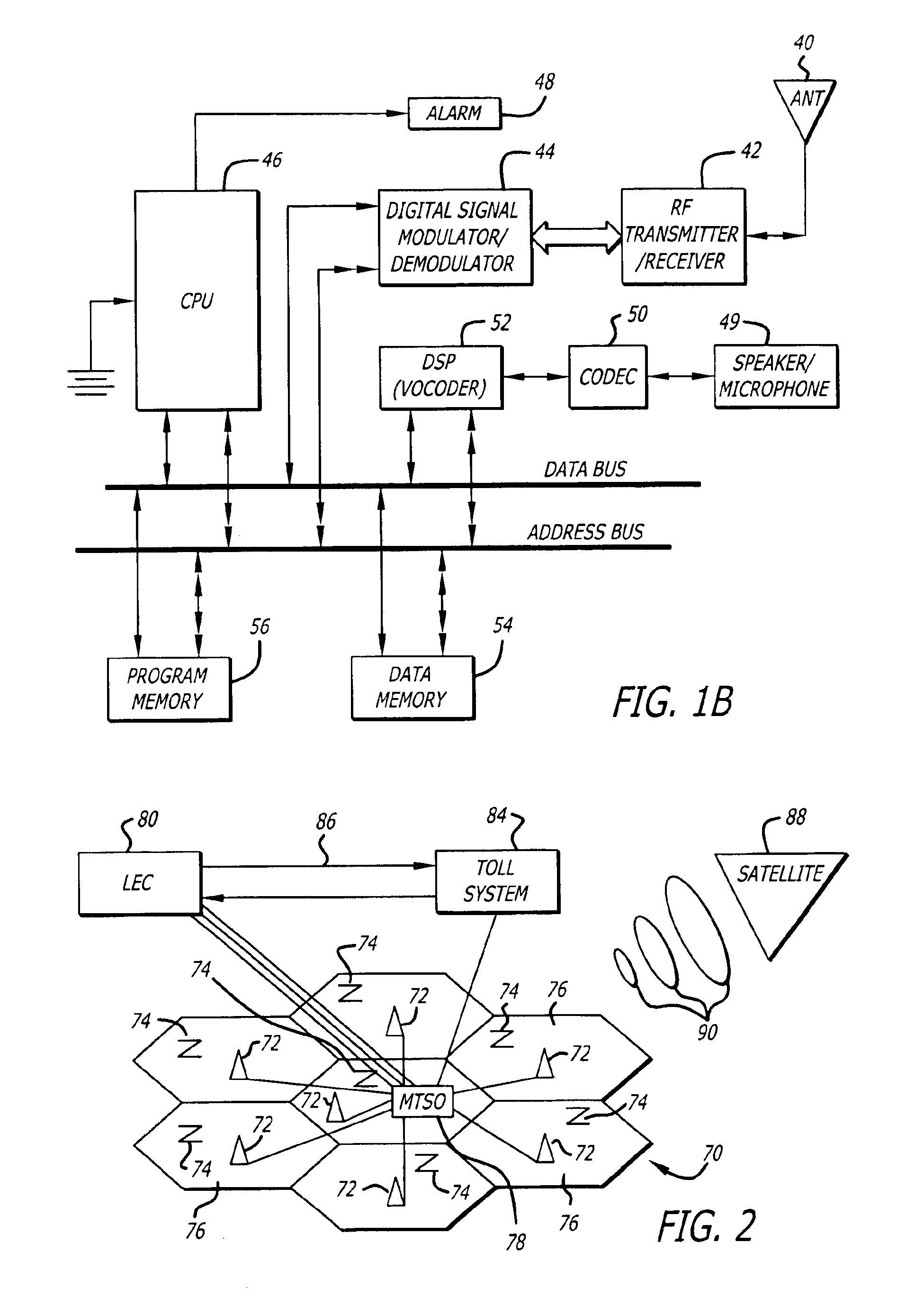
A system and method for a call receiving pager apparatus, system and method utilizing a dedicated switch for providing proprietary access, billing functions and other enhanced features is described. The system utilizes a subscriber apparatus having pager or radiotelephone functions whereby a caller may call the apparatus and gain direct two-way communication with the subscriber. The caller is billed for the communication. A call receiving pager apparatus, system and method wherein a subscriber can initiate an outgoing connection to at least one predetermined telephone number in order to send a pre-recorded voice or data message is also provided. The subscriber is unable to initiate any real time two-way communication with the outgoing connection.

Description

FIELD OF THE INVENTIONThe present invention relates generally to a call receiving pager apparatus, system, and method utilizing a dedicated switch which employ two-way wireless communication that can only be initiated by, and billed to, a caller. The call receiving pager system and method utilizes paging signals or cellular signals to create a two-way wireless communication connection between an outside caller and a pagephone / call receiving pager apparatus user / subscriber. More particularly, the present invention is directed to a call receiving pager apparatus, system and method which utilizes a subscriber paging apparatus capable of receiving pager signals or cellular signals and an outside dedicated switching system to generate two-way wireless communication by an outside caller calling a subscriber's page number wherein the caller is billed for the communication time and the subscriber is unable to incur communication charges due to their inability to initiate a direct two-way wi...

Claims


Application Information

Patent Timeline
Patent Type & Authority Patents(United States)
IPC IPC(8): H04M3/42H04M15/00H04Q7/38H04M3/533H04M7/12H04M3/50H04W4/12H04W4/24H04W4/90H04W8/26H04W12/08H04W68/00H04W76/02H04W88/06
CPCH04M3/42195H04M15/00H04M15/41H04W4/24H04W76/021H04W88/06H04M7/12H04M2215/0164H04M2215/2026H04M2215/32H04M2242/04H04W4/12H04W4/22H04W8/26H04W68/00H04W76/007H04W76/02H04M3/533H04W76/50H04W4/90H04W76/10H04W76/11
Inventor SCALISI, JOSEPH F.
Owner LBT IP LLC
Why Eureka
Try Eureka