
Control device for a laboratory centrifuge

a control device and laboratory technology, applied in the direction of centrifuges, alarms, visible signalling systems, etc., can solve the problems of inability to exclude operating errors, danger of operational errors, and comparatively complex operation of laboratory centrifuges, so as to avoid operational errors

Inactive Publication Date: 2005-04-12
SIGMA LABORZENTRIFUGEN
View PDF14 Cites 13 Cited by
  • Summary
  • Abstract
  • Description
  • Claims
  • Application Information

AI Technical Summary

Benefits of technology

It is the object of the invention to develop an actuating device specifically for a laboratory centrifuge, for controlling operating parameters and control functions for the operation of the laboratory centrifuge, whose operation in comparison with the illustrated prior art is simpler, faster, error-free and in particular multilingual. This object is achieved with a control device for controlling operating parameters and control functions for the operation of a laboratory centrifuge, the control device including a display panel for displaying a visual representation of at least a part of the operating parameters and control functions. A control switch is provided for setting the operating parameters and control functions. The control switch is capable of at least two independent movements, a first of the movements including a rotation about an axis and a second of the movements including a displacement along the axis. The display panel is configured to display the visually represented operating parameters and control functions in response to movement of the control switch. One of the movements provides for selection and change in setting of one of the operating parameters and controls functions and another of the movements provides for acceptance of the selection and acceptance of the setting.
According to another feature of the invention, the control switch is located in a central position below the display panel. This means that, in spite of the spatial proximity of control switch and display panel, neither for a left-handed or right-handed user is the visibility of the display panel hindered during the actuation of the control switch. This is a preferred arrangement of the control switch, which simultaneously makes possible a simple successful control of the inputted switch functions from the display panel for both left-handed and right-handed operators should remain guaranteed.
The control device of the present invention thus constitutes an operating means for the setting of operational parameters and control functions of a laboratory centrifuge which can be handled extremely simply, which is self-explanatory in terms of its functions on the basis of a menu guide, and which on the basis of the bringing together of all the setting functions into one single control switch in a special way means that one can avoid operational errors.

Problems solved by technology

Consequently, data specific to the rotor, the receptacles and the mixtures of substances are entered into appropriate storage media of the control device of the laboratory centrifuge, from which, depending upon the absolute volume of the data to be entered and of the control functions to be activated or to be inactivated, costly setting procedures result, which make necessary a correspondingly equipped control panel for the control device.
Again in dependence upon the complexity of the switching and entry devices for data and functions necessary in this connection, the operation of a laboratory centrifuge turns out to be comparatively complex, in particular its change over, for example to another treatment program, with the result that operating errors cannot be excluded.
For this it is essential that, in order to call up as well as to change, the course of operations of the laboratory centrifuge, namely to produce operating procedures appropriate to different materials to be handled, it is necessary to actuate a relatively large number of function keys, which brings with it the danger of operational errors and in any case a relatively costly training for the operator in order reliably to master the frequently complex setting procedures.

Method used


Image

  • Control device for a laboratory centrifuge
  • Control device for a laboratory centrifuge
  • Control device for a laboratory centrifuge

Examples


Embodiment Construction

The invention will not be described in more detail with reference to the embodiment which is given by way of example and which is shown in the drawings. In the drawings:

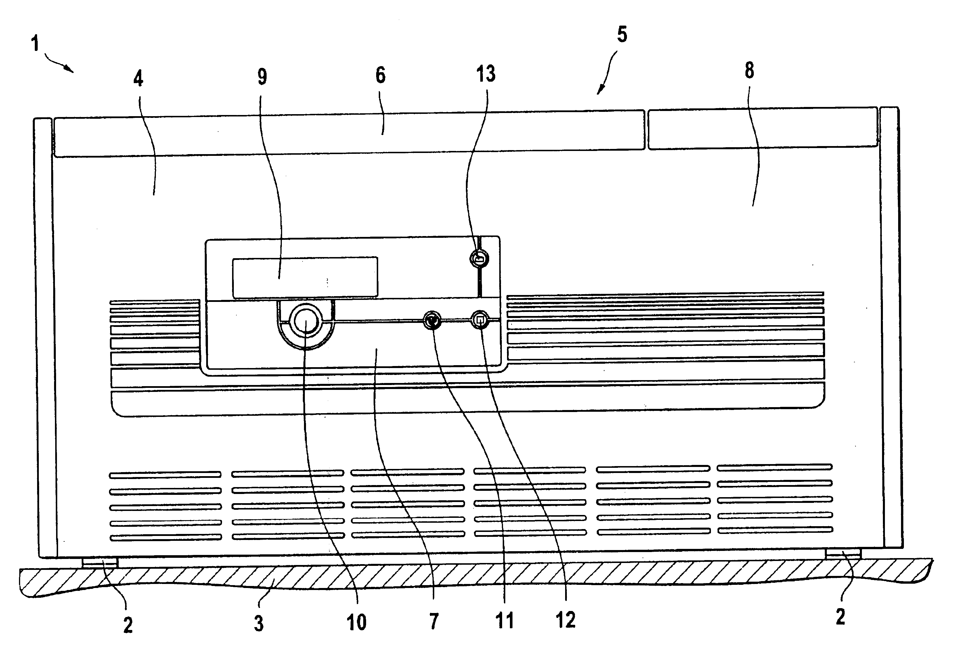
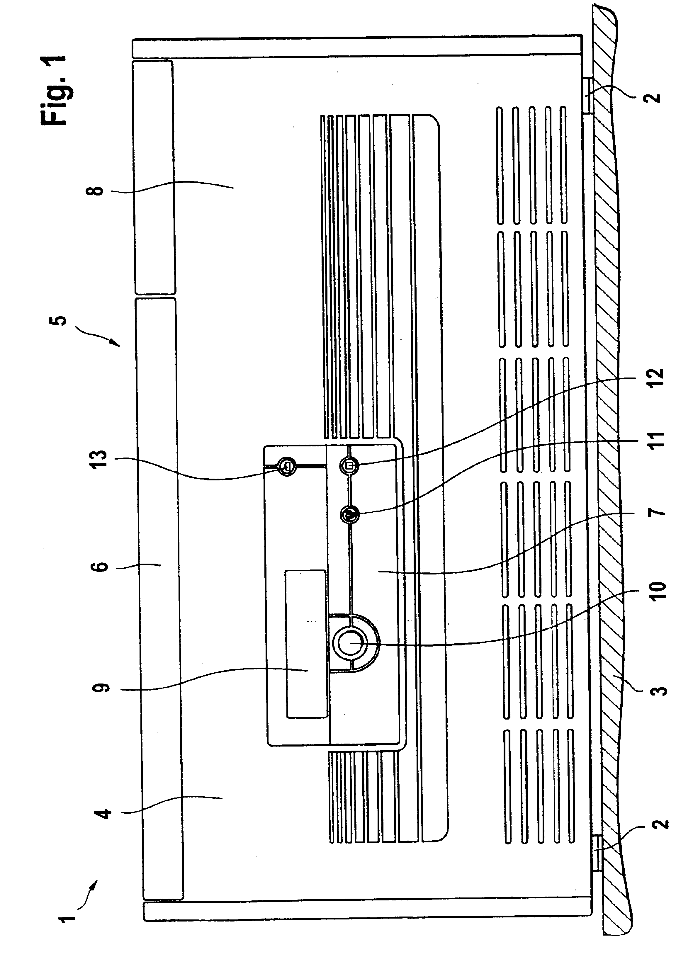
FIG. 1 is a representation of the front-end view of a laboratory centrifuge with control panel according to the invention;

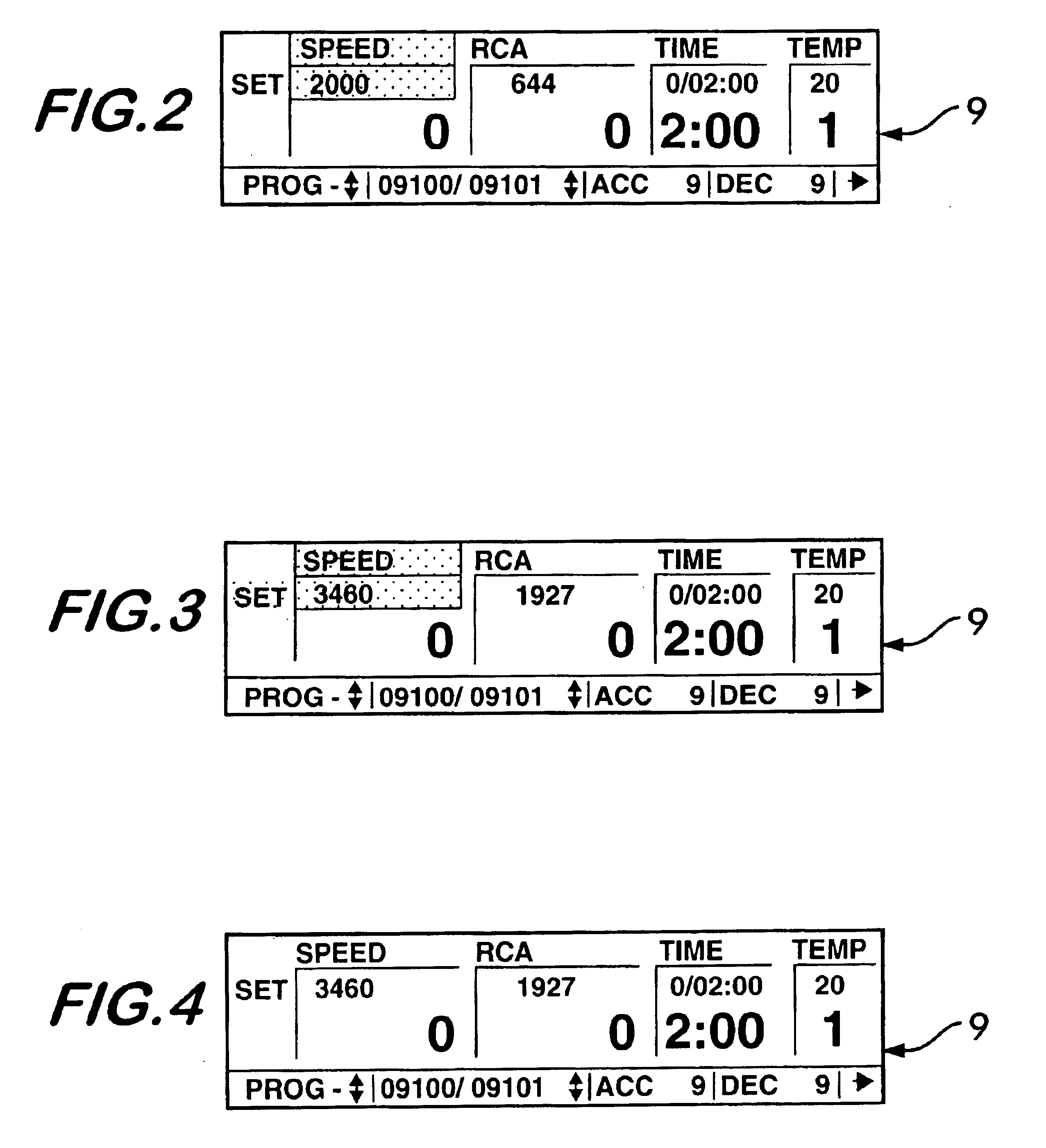
FIGS. 2 to 11 show diverse menu configurations controllable by means of the control panel according to the invention.

In FIG. 1 the reference numeral 1 indicates a laboratory centrifuge equipped with a control device according to the invention, the centrifuge being supported by means of support feet 2 on a base 3. It consists essentially of an overall rectangular housing 4, whose top 5 is closed off by a cover 6 which is pivotable about a horizontal axis between a closed position as shown in the drawing and an open position.

Within the housing there is located a rotor which is mounted to be rotatable about a vertical axis and which is set up in the peripheral region for the releasable receiving of r...


PUM


Abstract

A control device for controlling operating parameters and control functions for the operation of a laboratory centrifuge. The control device has a panel for displaying a visual representation of at least a part of the operating parameters and control functions such as speed of rotation, acceleration temperature, etc. A control switch sets the operating parameters and control functions, this switch being capable of at least two independent movements—a first movement including a rotation about an axis, the second one a displacement along the axis. One of these switch movement, e.g., rotation, provides for the selection and change in setting of one of the operating parameters and control functions, and another of the switch movement, e.g., displacement, provides for acceptance of the selection and acceptance of the setting.

Description

BACKGROUNDThe invention relates to a control device for a laboratory centrifuge, and more particularly to a laboratory centrifuge having a control panel which includes a display panel and switching devices for the operation of the centrifuge.Laboratory centrifuges are used inter alia in the medicinal-pharmaceutical field for the treatment of mixtures of substances by centrifuging, if necessary in accordance with a particular treatment time and a particular temperature curve. Such centrifuges consist essentially of a housing which can be closed by a lid, and within which is arranged a replaceable rotor whose peripheral portion is arranged to receive receptacles which are likewise replaceable, and in which the mixtures of substances to be treated are placed. The rotor is connected to an electrical drive and the total system consisting of rotor and electric motor is arranged to be able to oscillate within the housing.In dependence upon the inserted rotor as well as in dependence on the...

Claims


Application Information

Patent Timeline
IPC IPC(8): B04B13/00
CPCB04B13/00
Inventor TODTEBERG, ECKHARDBENDER, MICHAEL
Owner SIGMA LABORZENTRIFUGEN
Learn More