Transreflective liquid crystal display and method of manufacturing the same

a liquid crystal display and transreflective technology, applied in non-linear optics, instruments, optics, etc., can solve the problems of power consumption increase, difference in color reproducibility etc., to reduce the number of manufacturing processes, the difference in color reproducibility and the brightness between reflective and transmissive modes

Inactive Publication Date: 2005-04-12
SAMSUNG DISPLAY CO LTD
View PDF13 Cites 28 Cited by
  • Summary
  • Abstract
  • Description
  • Claims
  • Application Information

AI Technical Summary

Benefits of technology

According to the present invention, a size of the first area of the reflective electrode is smaller than that of the second area of the transmissive electrode exposed through the transmissive window, so that the differences of the color reproducibility and the brightness between the r

Problems solved by technology

If the amount of the second light increases to compensate the brightness difference, the power consumption increase

Method used


Image

  • Transreflective liquid crystal display and method of manufacturing the same
  • Transreflective liquid crystal display and method of manufacturing the same
  • Transreflective liquid crystal display and method of manufacturing the same

Examples


embodiment 1

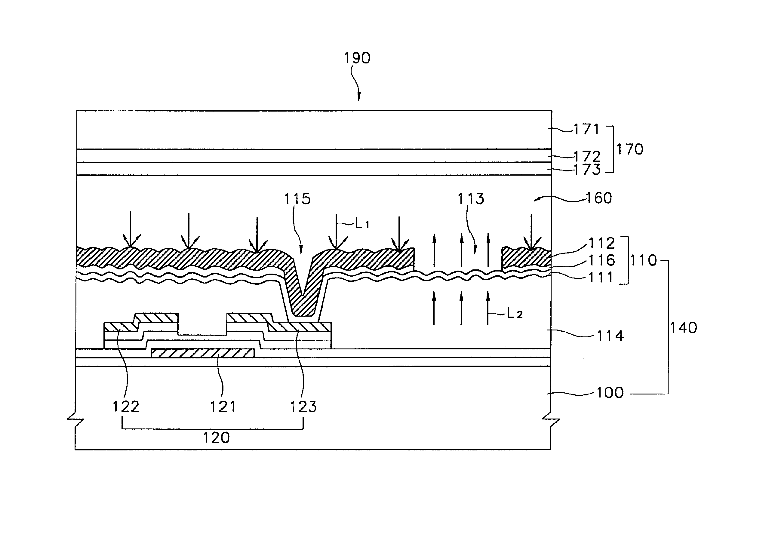
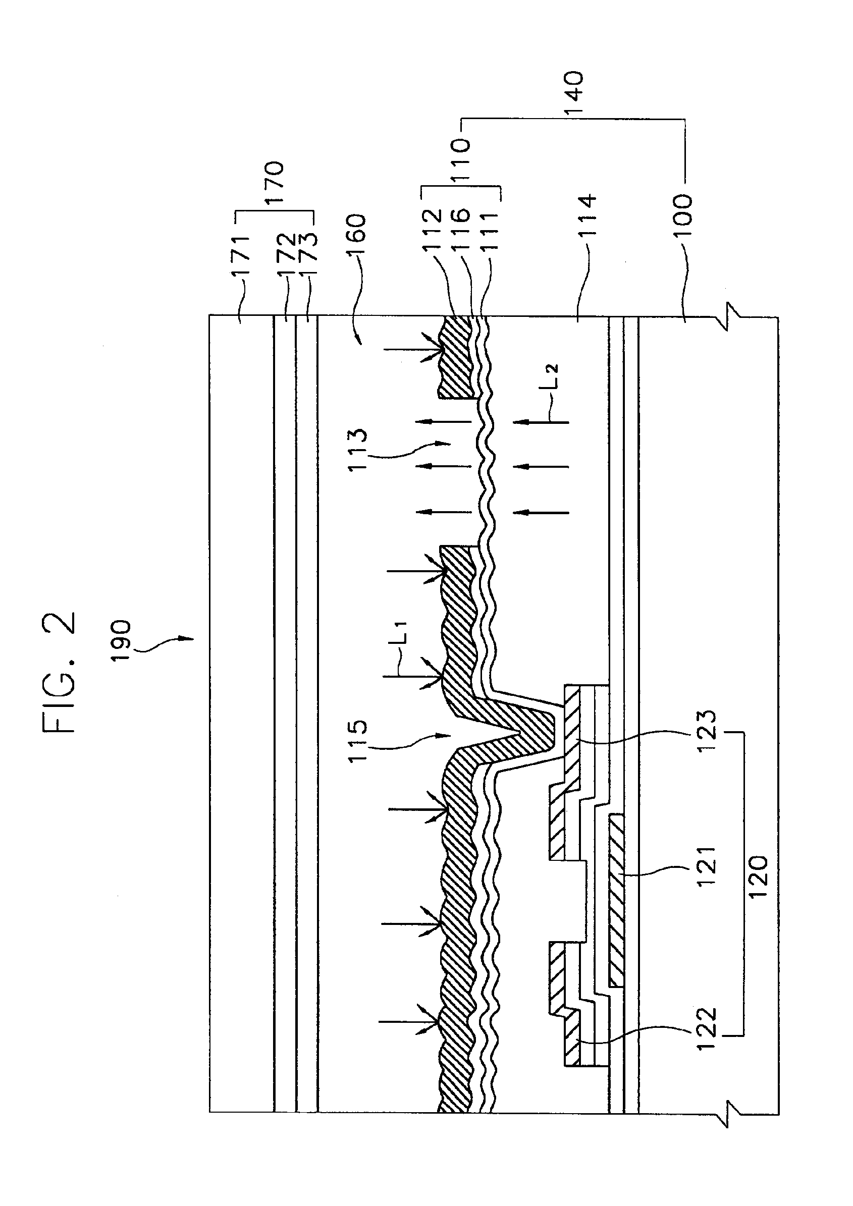
FIG. 2 is a cross-sectional view showing a transreflective type LCD manufactured according to a first embodiment of the present invention.

Referring to FIG. 2, the transreflective type LCD 190 includes a TFT substrate 140, a color filter substrate 170 facing the TFT substrate 140 and a liquid crystal layer 160 interposed between the TFT substrate 140 and the color filter substrate 170.

The TFT substrate 140 includes a first insulation layer 100, a TFT 120 disposed on the first insulation layer 100, a first organic insulation layer 114 formed with a contact hole 115 on the TFT 120, a transmissive electrode 111 formed on the first organic insulation layer 114, a second organic insulation layer 116 formed on the transmissive electrode 111, a transmissive window 113 and a reflective electrode 112 electrically connected to the transmissive electrode 111. The first insulation layer 100 is made of a transparent material.

The TFT 120 is formed on the first insulation layer 100. The TFT 120 inc...

embodiment 2

FIG. 8 is a cross-sectional view showing a transreflective type LCD according to a second embodiment of the present invention.

Referring to FIG. 8, a transreflective type LCD 200 includes a TFT substrate 250, a color filter substrate 260 facing the TFT substrate 250 and a liquid crystal layer 270 interposed between the TFT substrate 250 and the color filter substrate 260.

The TFT substrate 250 includes a first insulation substrate 210 on which a plurality of pixels is formed. Each of the pixels includes a TFT 220 having a gate electrode, a source electrode and a drain electrode, an image maintaining capacitance 227 including a lower electrode 221a and an upper electrode reflection plate 226a which reflects a first light, and a transmissive electrode 240 for controlling an alignment of the liquid crystal 270 in response to a power voltage supplied from the TFT 220 and transmitting the first light at a region other than a region corresponding to the upper electrode reflection plate 226a...

embodiment 3

FIG. 11 is a cross-sectional view showing a unit pixel of a transreflective type LCD according to a third embodiment of the present invention.

Referring to FIG. 11, a transreflective type LCD 600 includes a TFT substrate 500, a color filter substrate 300 facing the TFT substrate 500 and a liquid crystal layer 400 interposed between the TFT substrate 500 and the color filter substrate 300.

The TFT substrate 500 includes a plurality of pixels. Each of the pixels includes a TFT 550, a transmissive electrode 548 connected with a drain electrode 546 of the TFT 500 and used as a first electrode of an image maintaining capacitance 560 and a first image maintaining reflective electrode 526 formed to have a height identical with that of a gate electrode 522 of the TFT 550 and used as a second electrode of the image maintaining capacitance 560. The first image maintaining reflective electrode 526 faces the transmissive electrode 548.

The color filter substrate 300 includes a second insulation su...


PUM


Abstract

Disclosed are a transreflective type LCD, a method of manufacturing the same and a method of thin film transistor thereof. A TFT and a pixel electrode connected with a drain electrode of the TFT are formed on a TFT substrate. The pixel electrode includes a reflective electrode for reflecting a first light from an external and a transmissive electrode for transmitting a second light generated in the transreflective type LCD. The reflective electrode is formed to have a size no more than a size of an area in which the reflective electrode is not overlapped with the transmissive electrode. Thus, visual differences between the reflective and the transmissive modes are reduced. Also, the reflective electrode for reflecting the first light is formed with the TFT through one process, thereby reducing the number of manufacturing processes of the transreflective type LCD and the thickness thereof.

Description

BACKGROUND OF THE INVENTION1. Field of the InventionThe present invention relates to a liquid crystal display (LCD), and more particularly to a transreflective type LCD and a method of manufacturing the same.2. Description of the Related ArtIn the so-called information society of these days, electronic display devices are important as information transmission media and various electronic display devices are widely applied to industrial apparatus or home appliances. Recently, demand has increased for a new electronic display device such as an LCD having characteristics such as thin thickness, light weight, low driving voltage and low power consumption. Manufacturing of such LCD has been improved due to advances in semiconductor technology.The LCD is classified as a reflective type LCD that displays an image using a first light provided from an external, a transmissive type LCD that displays an image using a second light generated by a light generating means installed therein, and a t...

Claims


Application Information

Patent Timeline
IPC IPC(8): G02F1/1335G02F1/13G02F1/1343G02F1/1368
CPCG02F1/133555G02F1/1335
Inventor MOON, KOOK-CHULYOON, JOO-SUNCHOI, PIL-MOYANG, YONG-HOAHN, YANG-SUKKIM, HONG-GYUNYON, YOUNG-NAM
Owner SAMSUNG DISPLAY CO LTD
Why Eureka
Try Eureka