Holographic spectral filter

a holographic and spectral filter technology, applied in the field of optical signal processing, can solve the problems of lack of flexibility, high cost, and inability to apply widely

Inactive Publication Date: 2005-04-12
STEYPHI SERVICES DE
View PDF29 Cites 90 Cited by
  • Summary
  • Abstract
  • Description
  • Claims
  • Application Information

AI Technical Summary

Problems solved by technology

In many cases these shortcomings, including limited spectral resolution, alignment sensitivity, fabrication difficulties, high cost, and lack of flexibility, have prevented widespread application.
The dual-grating, free-space spectral filtering device has limited appeal in the context of communication systems because of its physical complexity, sensitivity to precision alignment, relatively large insertion loss, and limited spectral resolution for gratings of tractable physical dimensions.
Programmed diffractive structures known in the art do not provide for the implementation of general wavefront transformations simultaneously with general spectral transformations.
Programmed surface gratings and programmed fiber gratings are encumbered with severe functional constraints.
A programmed surface-grating filter has a fundamentally low efficiency, and requires alignment sensitive free-space optical elements to function.
Programmed fiber-grating filters produce output signals that are difficult to separate from input signals (since they can only co- or counterpropagate), and can only support a single transfer function within a given spectral window.
However, programmed surface-grating filters have a very serious deficiency in their intrinsically low efficiency.
As a result, the higher the complexity of the programmed transfer function (and therefore, the more sine components needed to describe it), the lower the efficiency of the programmed surface grating filter.
Programmed fiber Bragg filters are useful, but have significant limitations.
A primary drawback is that there is only one input direction 506 and one output direction 508, those directions being antiparallel (transmitted signals are not often employed.)
Furthermore, a circulator 504, used to separate input and output signals is costly, and adds complexity to the overall device.
Finally, programmed fiber Bragg gratings are time-consuming and labor-intensive to fabricate.
Fabrication typically requires complex masking and high power ultraviolet exposure for extended time periods, or complicated ultraviolet holographic exposure apparatus with long exposure times.
There have been filters disclosed comprising systems of uniform diffractive elements, that offer the capability of applying a specific type of spatial wavefront transformation to input signals, but that do not possess the capability of implementing general spatial or spectral transformations.

Method used


Image

  • Holographic spectral filter
  • Holographic spectral filter
  • Holographic spectral filter

Examples


Embodiment Construction

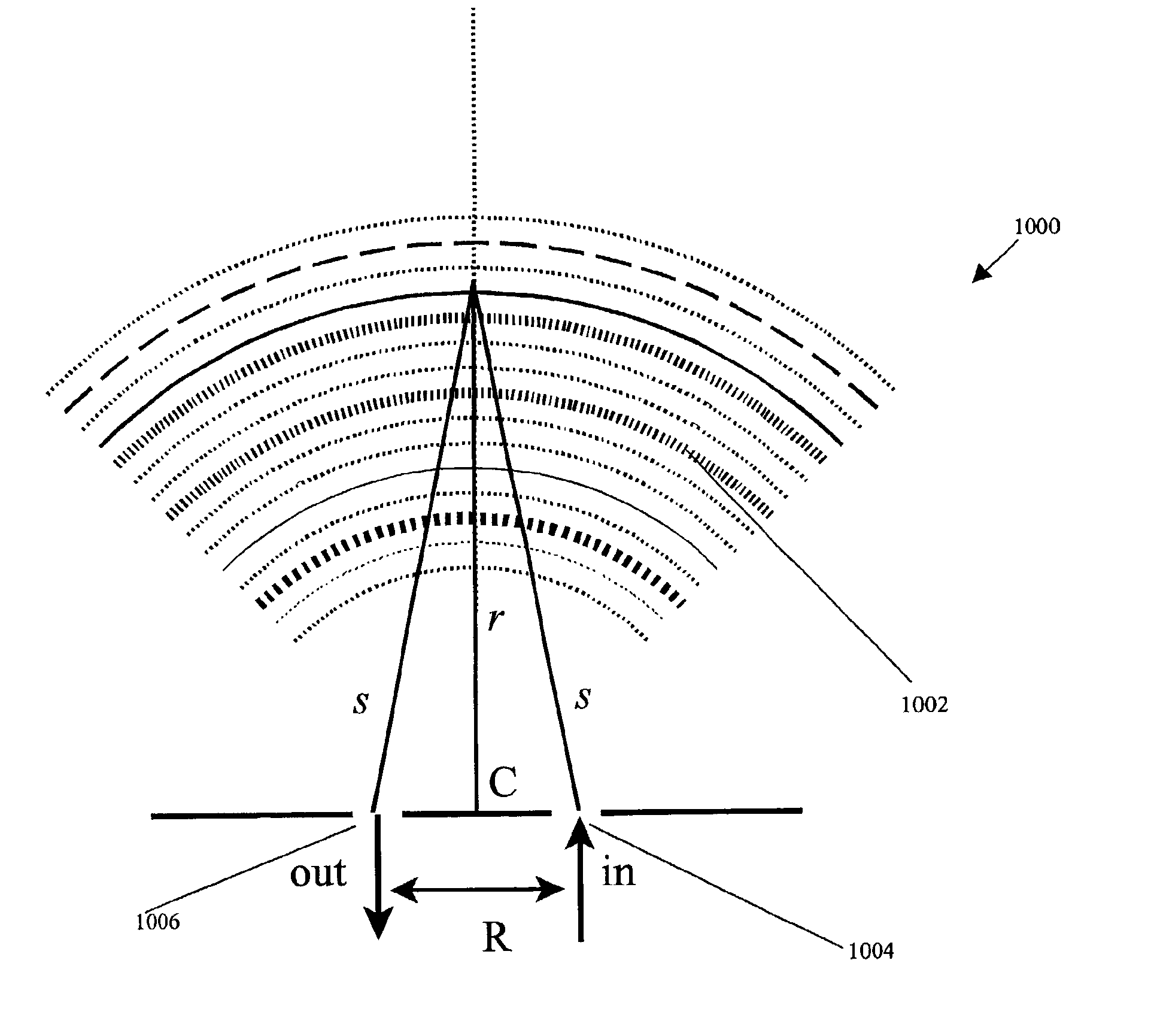
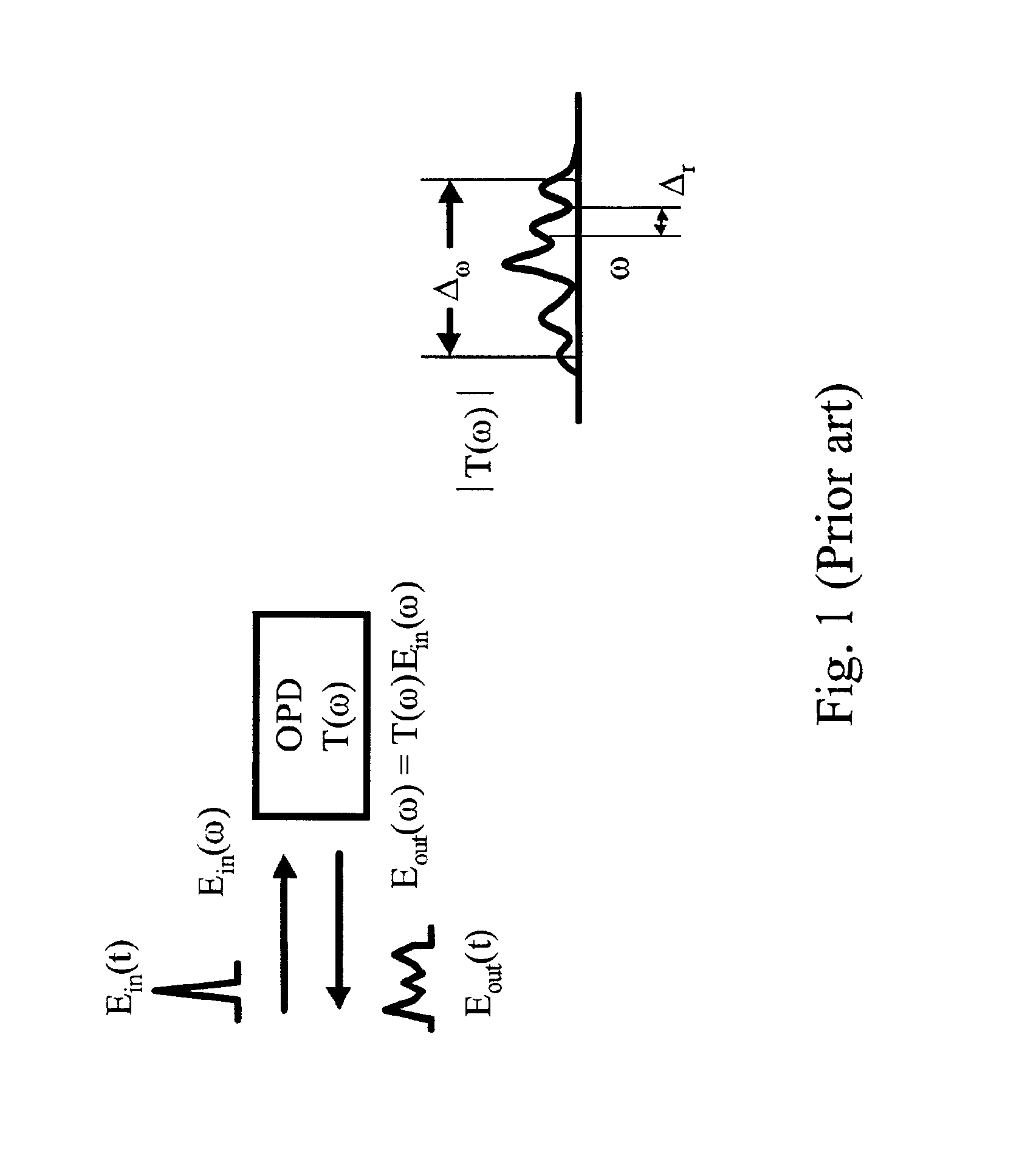
The present invention contemplates a new class of spectral filtering devices, which we refer to as programmed holographic spectral filtering devices, or more simply and interchangeably as programmed holographic devices or programmed holographic processors. These spectral filtering devices are free of the shortfalls of previous spectral filtering devices, and yet provide low cost, high performance functionality. Programmed holographic devices comprise volume holograms in substrates that may comprise planar waveguides, bulk materials, or other substrates, whose diffractive elements have spatial variations in amplitude, optical spacing, or spatial phase, whose detailed form dictates the transfer function produced by the device. A volume hologram is a diffractive structure operative to generate output optical signals in response to input optical signals, wherein each portion of the wavefront of the input signal contributes to the output signal by scattering from the diffractive structur...


PUM


Abstract

Method and apparatus are contemplated for receiving from an input, an optical signal in a volume hologram comprising a transfer function that may comprise temporal or spectral information, and spatial transformation information; diffracting the optical signal; and transmitting the diffracted optical signal to an output. A plurality of inputs and outputs may be coupled to the volume hologram. The transformation may be a linear superposition of transforms, with each transform acting on an input signal or on a component of an input signal. Each transform may act to focus one or more input signals to one or more output ports. A volume hologram may be made by various techniques, and from various materials. A transform function may be calculated by simulating the collision of a design input signal with a design output signal.

Description

FIELDThe field of interest is optical signal processing.BACKGROUNDSpectral filtering is a very useful optical function that can be utilized to control the temporal waveform of pulsed optical signals, cross-correlate or otherwise process optical signals, and to differentially control and manipulate spectrally-distinguished optical communication channels, as found for example in wave-division-multiplexed (WDM) optical communication systems. Devices have been introduced over the years to perform spectral filtering, all of which have characteristic shortcomings along with their strengths. In many cases these shortcomings, including limited spectral resolution, alignment sensitivity, fabrication difficulties, high cost, and lack of flexibility, have prevented widespread application.A spectral filtering device, according to the present usage, is a device that applies a fixed or dynamically re-programmable, complex-valued, spectral transfer function to an input signal. If Ein(ω) and Eout(ω...

Claims


Application Information

Patent Timeline
Patent Type & Authority Patents(United States)
IPC IPC(8): G02B6/124G02B5/20G02B5/32G02B6/34G03H1/04G02B6/12
CPCG02B5/203G02B5/32G02B6/12007G02B6/124G02B6/29326G02B6/29398G03H1/0248G02B6/29328Y10S359/90G02B2006/12164G03H1/0005
Inventor MOSSBERG, THOMAS
Owner STEYPHI SERVICES DE
Why Eureka
Try Eureka