[0011]We have found that use of a region of lower
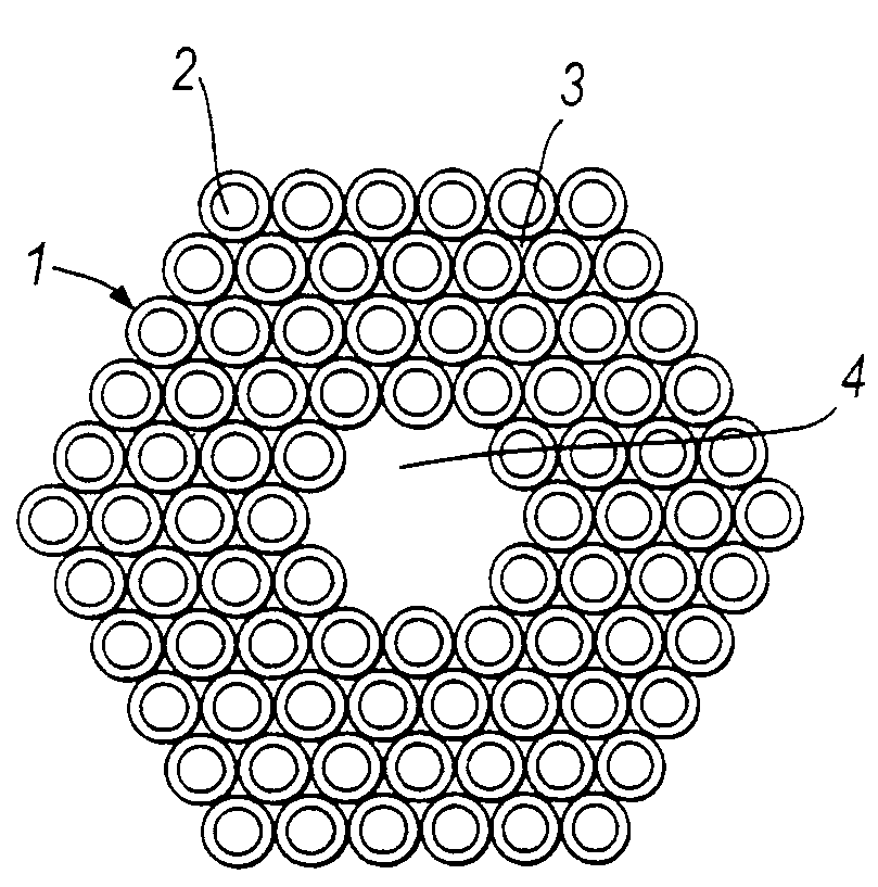
refractive index which is relatively large enables guidance to be achieved in the region of lower refractive index and we have made a fibre in which light is guided, substantially without leakage, in a
hollow core. It will be understood that the region of “lower” refractive index has a refractive index which is smaller in magnitude than the refractive index of the region of higher refractive index.
[0014]Ultra-high power single-mode transmission, possibly even of light which is strongly absorbed by
silica glass such as that from a CO2
laser, is a possible application of such a fibre. High power
laser light delivery is another application, which also makes use of the ability of the fibre to transmit much
higher power than a conventional fibre; delivery of 100 W to 1 kW to a
machining head, from a large-frame
laser, is, for example, a recurrent need.
High power lasers represent an area with broad applications in, for example, high speed printing, laser
machining of materials, and possibly
surgery; fibre lasers are efficient, offering a high power per kg. Their compactness, and the high quality of the beams they produce, make them very attractive in all kinds of portable laser apparatus.
[0019]Guidance in a lower-index region is possible because the photonic
band gap material of the fibre cladding can behave in a manner similar in some respects to a totally reflecting, perfect
metal under some circumstances but, unlike real metals, such a quasi-
metal exhibits very low losses at
optical frequencies. The photonic
band gap material behaves like a
metal when it exhibits a full two-dimensional photonic band gap; that is, when light propagating with a particular wavevector component along the fibre and at a particular frequency sees, at all azimuthal angles, material having a band gap. Only certain
wavelength bands are confined and guided down the fibre, those bands corresponding to the presence of full two-dimensional band gaps in the photonic
crystal cladding.
[0020]The wavevector component along the
waveguide, known as the
propagation constant β, determines whether light is propagating or evanescent in any part of the guide. If β<kn, the light propagates at an angle θ to the axis in a material of refractive index n, where β=kn cos θ and k is the vacuum wave constant. If β>kn, θ is imaginary and the light is evanescent. Conventional
total internal reflection, with a core of index n1 greater than the cladding index n2 ensures the existence of a range of β where light is propagating in the core while being evanescent in the cladding.
[0023]In both forms of photonic band gap guidance, the refractive index of the core can be chosen much more freely than in total internal reflection guidance, because the photonic band gap conditions depend only on the properties of the cladding stacks. Guided
modes can exist with mode indices β / k that are lower than the “mean” index of the stacks (the frustrated tunneling guidance case) or even lower than the lowest index of the stacks (the Bragg guidance case), conferring extra design freedom over total internal reflection guidance, and allowing confinement within a
hollow core.
[0032]Optical properties of the fibre can be accurately computed once the fibre size is fixed. The photonic band gap of the periodic fibre cladding can extend over a broad range of frequencies; however, in general, the mode will be guided in the lower-index region only over a relatively
narrow range of frequencies. The
narrowband performance of the fibre suggests that it should be useful as a
spectral filtering device.

