
Spectral selection and image conveyance using micro filters and optical fibers

a technology of optical fibers and micro filters, applied in the field of spectrometers, fiber optics, fiber optic systems, etc., can solve the problems of loss of color information, light can couple into adjacent spectral bands, and glass optical fibers of fiber optic cables have very small diameters

Active Publication Date: 2006-01-26
UTAH STATE UNIVERSITY
View PDF15 Cites 51 Cited by
  • Summary
  • Abstract
  • Description
  • Claims
  • Application Information

AI Technical Summary

Benefits of technology

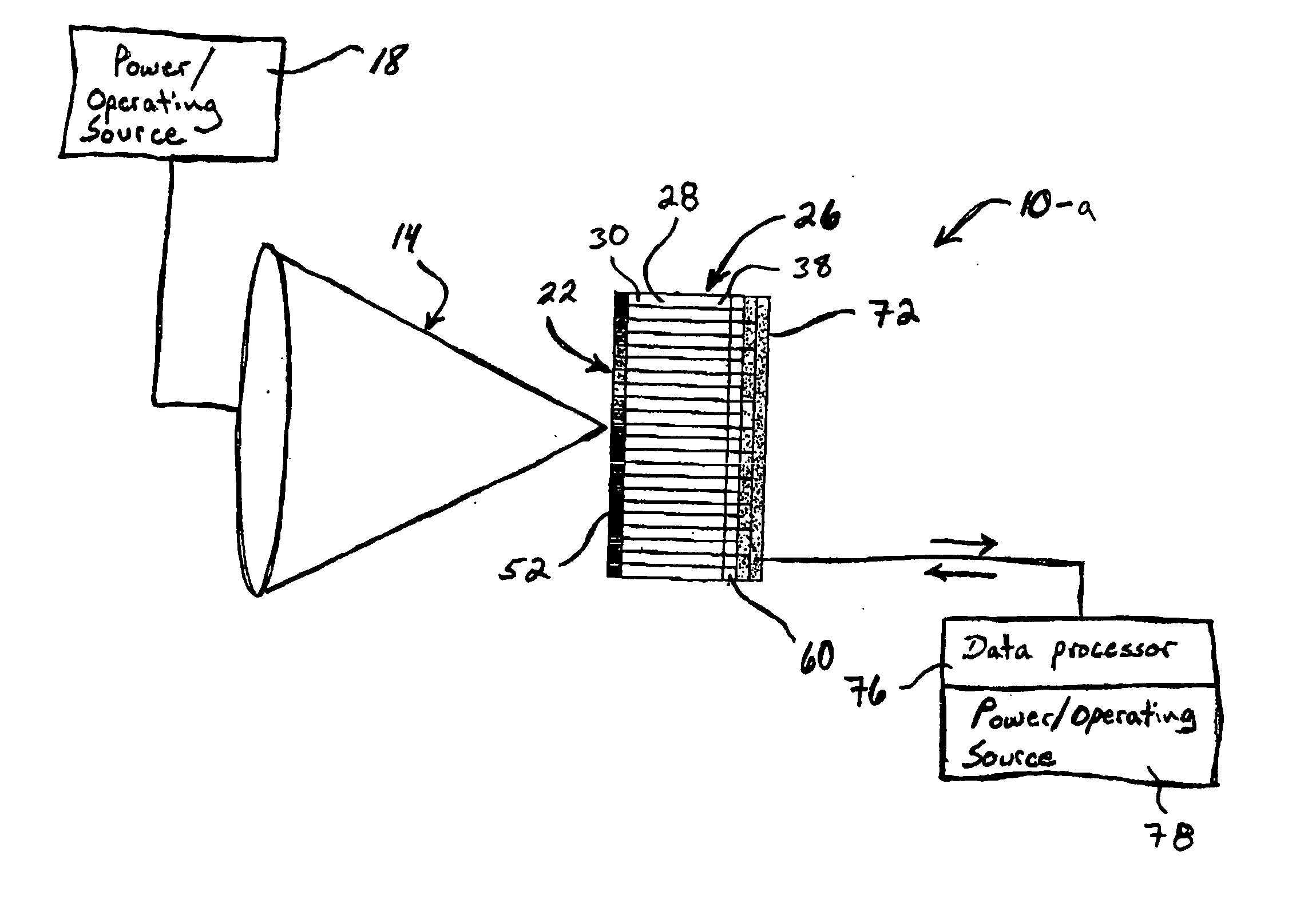
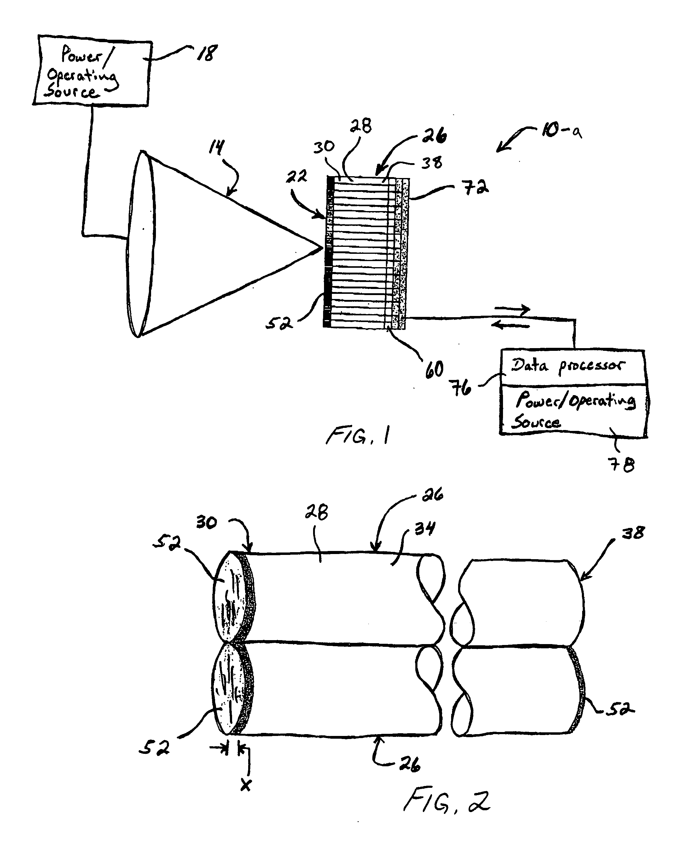
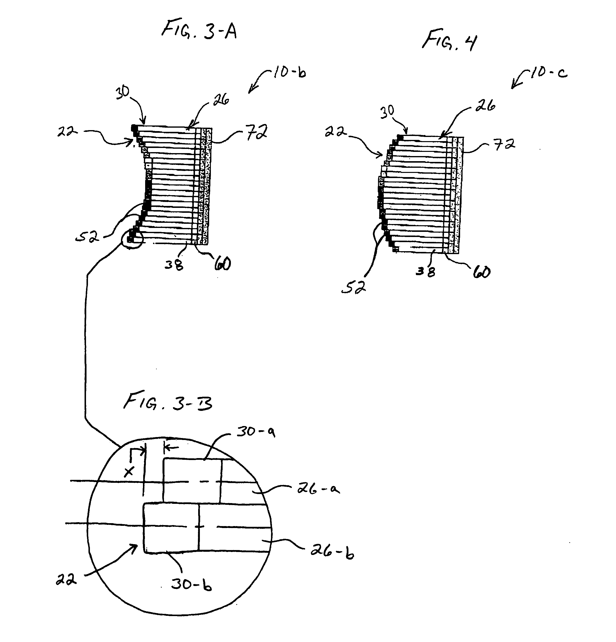
[0010] In accordance with the invention as embodied and broadly described herein, the present invention features an imaging system comprised of one or more fiber optic elements optically coupled to a detector or an array of detectors, otherwise known as an imaging array, wherein the imaging system functions to eliminate the need for a substrate filter coupled to the imaging array. The fiber optical elements are further optically coupled to a spectral filter having a specific passband, which spectral filter is preferably in the form of a coating applied directly to one or more ends of the fiber optic elements, such that each fiber optic element is provided a specific, pre-determined optical energy transmittance capacity, which is based on the passband of the spectral filter. In other words, each fiber optic element is configured to transmit from its output end only a narrow portion of the available optical energy (i.e., only a specific wavelength or range of wavelengths), which transmitted optical energy is optimally transmitted by the fiber optic element. Providing the fiber optic elements with a specific and pre-determined optical energy transmittance capacity may be accomplished by depositing a single coating at one end of the fiber optic element, or by depositing coatings at both ends. In one embodiment, one end of the fiber optical element is placed at or optically coupled to the focal surface of an optical system, while the other end is placed on, in close proximity to, or otherwise optically coupled to the detector or imaging array to form an imaging system.

Problems solved by technology

The glass optical fibers of fiber optic cables have very small diameters, which are susceptible to external influences such as mechanical stress and environmental conditions.
This monochromatic or single spectral band type of sensor would record overall irradiance at the pixel but would result in a loss of color information.
The disadvantage of the traditional filter substrate approach is that light can couple into adjacent spectral bands.

Method used


Image

  • Spectral selection and image conveyance using micro filters and optical fibers
  • Spectral selection and image conveyance using micro filters and optical fibers
  • Spectral selection and image conveyance using micro filters and optical fibers

Examples


Embodiment Construction

[0030] The following detailed description of exemplary embodiments of the invention makes reference to the accompanying drawings, which form a part hereof and in which are shown, by way of illustration, exemplary embodiments in which the invention may be practiced. While these exemplary embodiments are described in sufficient detail to enable those skilled in the art practice the invention, it should be understood that other embodiments may be realized and that various changes to the invention may be made without departing from the spirit and scope of the present invention. Thus, the following more detailed description of the embodiments of the present invention, as represented in FIGS. 1 through 11, is not intended to limit the scope of the invention, as claimed, but is presented for purposes of illustration only and not limitation to describe the features and characteristics of the present invention, to set forth the best mode of operation of the invention, and to sufficiently ena...


PUM

PropertyMeasurementUnit
optical energyaaaaaaaaaa
transmittanceaaaaaaaaaa
wavelengthsaaaaaaaaaa

Abstract

The present invention features a fiber optic imaging system for generating a customized spectral response comprising (a) an optional optical source for generating optical energy, (b) an optical system for focusing multi spectral optical energy to form a focal surface; (b) a fiber optic element for conveying the optical energy, wherein the fiber optic element has an input end optically coupled to the focal surface to receive the optical energy and an output end to transmit the conveyed optical energy; and (c) a spectral filter optically coupled to at least one of the input and output ends of the fiber optic element, wherein the spectral filter has a filter passband configured to provide the fiber optic element with a pre-determined wavelength transmittance capacity, such that only pre-determined wavelengths of the optical energy are transmitted through the output end, thus achieving a customized spectral response. The fiber optic imaging system may further comprise an imaging array optically coupled to the output end of the fiber optic element and configured to gather the transmitted optical energy and to convert it into a data signal corresponding to an image based on the customized spectral response. An example of this type of configuration is a spectrometer.

Description

RELATED APPLICATIONS [0001] This application claims priority to U.S. Provisional Application Ser. No. 60 / 587,064, filed Jul. 12, 2004, and entitled, “Spectral Selection and Image Conveyance using Micro Filters and Optical Fibers,” which is incorporated by reference herein in its entirety.FIELD OF THE INVENTION [0002] This invention relates to imaging spectrometers, fiber optics, and fiber optic systems, and particularly to a spectral selection and image conveyance system using optical fibers, wherein the optical fibers comprise a specific transmittance wavelength capacity. BACKGROUND OF THE INVENTION AND RELATED ART [0003] Various systems and devices utilizing fiber optics to convey optical energy, such as an image, are well known in the art. In addition, the use of fiber optical elements near focal planes is also well known in the art. Indeed, fiber optics technology is utilized in a wide variety of applications for transmitting voice, video, and data signals. Fiber optic cables ha...

Claims


Application Information

Patent Timeline
Patent Type & Authority Applications(United States)
IPC IPC(8): G01N21/25
CPCG01J3/02G01J3/0218G01J3/0256G01J2003/1239G01J3/2803G01J3/51G01J3/513G01J3/0262
Inventor CROWTHER, BLAKE G.
Owner UTAH STATE UNIVERSITY
Learn More