Power source inverter circuit

a technology of inverter circuit and power source, which is applied in the direction of power conversion system, dc-dc conversion, instruments, etc., can solve the problems of slow rise of the voltage of the storage means, inability to charge, and extremely long activation time, so as to achieve efficient use of electric power

Inactive Publication Date: 2005-04-12
ABLIC INC
View PDF4 Cites 77 Cited by
  • Summary
  • Abstract
  • Description
  • Claims
  • Application Information

AI Technical Summary

Benefits of technology

The present invention has been made in view of the above-mentioned inconveniences of prior art, and an object of the present invention is therefore to provide a power source inverter circuit which, when power feeding means generates enough electric power, puts a load circuit into operation while storing electric power in storage means and, when the power feeding means stops generating power, efficiently uses up the electric power stored in the storage means.

Problems solved by technology

Accordingly, when the storage means has large capacity, the voltage of the storage means is slow to rise and activation takes extremely long.
In this case, charging cannot be conducted when there is a change in output voltage of the power feeding means and either raising or lowering the voltage cannot help the output voltage of the DC—DC converter from dropping below the output of the storage means.
Furthermore, the load circuit, which operates on electric power stored in the storage means after output of the power feeding means becomes unavailable, stops its operation once the voltage of the storage means drops below the minimum operation voltage of the load circuit.
This means that the excess electric power goes to waste.
In particular, power feeding means such as a solar module or a thermoelectric conversion circuit is quick to change its output voltage in response to a change in environment or with time, thereby making it difficult to maintain the same level of output performance.
Here lies another inconvenience because, in conventional power source inverter circuits where the amount of electric power to be taken out of the power feeding means is determined in accordance with power consumption of the load circuit, electric power is rarely taken out with the maximum power generation efficiency and the excess power is wasted.
Conventional power source inverter circuits, where the storage means and the load circuit are connected in parallel to the output of the rectifier element, have still another inconvenience: the storage empty of electric charges induces a voltage drop even when the output of the DC—DC converter is equal to or higher than the operation voltage of the load circuit and it is not until some electric charges are stored in the storage means that the load circuit can start its operation.
Furthermore, in conventional power source inverter circuits that use switched capacitor type DC—DC converters, the step-up multiple number or the step-down multiple number is fixed and therefore electric power cannot be stored once the output voltage of the DC—DC converter becomes lower than the voltage of the storage means irrespective of power conversion performed on the output power of the power feeding means which changes its output voltage with time or with a change in environment.
Yet another inconvenience is that the load circuit, which operates on electric power stored in the storage means when the power feeding means no longer generates power which changes its output voltage with time or with a change in environment, stops its operation as the voltage of the storage means drops below the minimum operation voltage of the load circuit.
A mere voltage drop renders the load circuit ineffective even though there are enough electric power left in the storage means.
Accordingly, the remaining electric power goes to waste.

Method used


Image

  • Power source inverter circuit
  • Power source inverter circuit
  • Power source inverter circuit

Examples


Embodiment Construction

Referring to the accompanying drawings, a detailed description will be given below on embodiments of a power source inverter circuit according to the present invention. A power source inverter circuit of this embodiment is for use in a portable instrument having as power feeding means a solar module, a thermoelectric conversion element, or a generator using a motor, which generates electric power varying in voltage and amount depending on environment and time, and aims at efficiently storing electric power generated and consuming the electric power with efficiency.

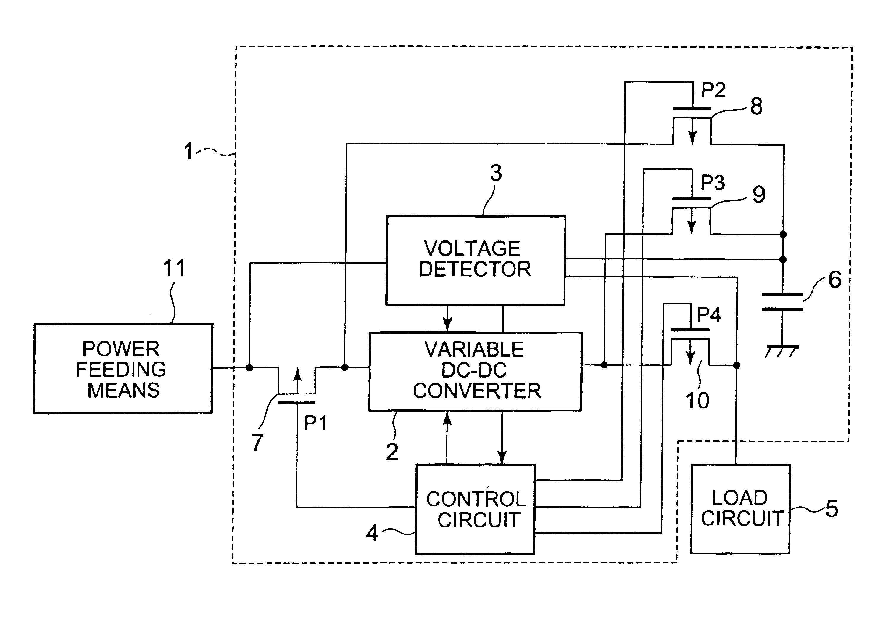
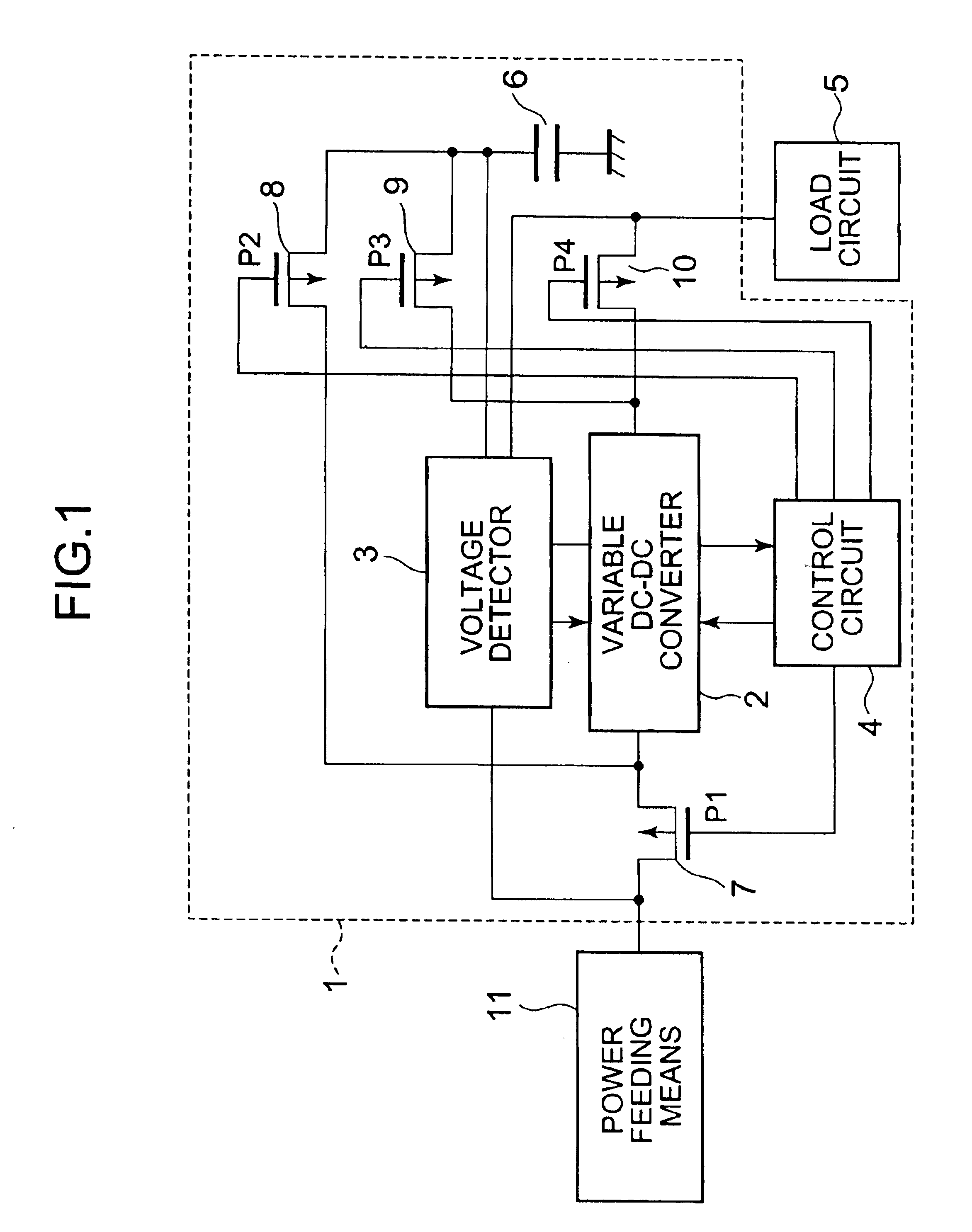
FIG. 1 is a block diagram showing an outline of a structure of a power source inverter circuit 1 according to this embodiment. The power source inverter circuit 1 of the present invention is composed of: a variable DC—DC converter 2 for raising or dropping the voltage of electric power which is supplied from power feeding means 11; a capacitor 6 for storing electric power whose voltage has been boosted or dropped by the va...


PUM


Abstract

A power source inverter circuit is provided which, when a feeding unit generates enough electric power, puts a load circuit into operation while storing electric power in a storage unit and, when the power feeding unit stops generating power, efficiently uses up the electric power stored in the storage unit. The power source inverter circuit is composed of: a variable DC—DC converter for raising or dropping a voltage of electric power that is supplied from the power feeding unit; the storage unit; MOSFET switches for connecting the power feeding unit and the storage unit to an input of the variable DC—DC converter and for connecting an output of the variable DC—DC converter to the storage unit and the load circuit; a control circuit for controlling gates of the MOSFET switches; and a voltage detector for monitoring output of the power feeding unit, the voltage of the storage unit, the input voltage of the load circuit, and for outputting voltage information to the variable DC—DC converter as well as to the control circuit.

Description

BACKGROUND OF THE INVENTION1. Field of the InventionThe present invention relates to a power source inverter circuit, more specifically, a power source inverter circuit for electronic instruments driven by use of output of a solar module or a thermoelectric conversion element in which electric power generated is supplied to a load circuit with efficiency and excess electric power is stored in storage means.2. Description of the Related ArtConventional power source inverter circuits supply a load circuit with electric power of power feeding means which changes its voltage and current with time or with a change in environment and have, as shown in FIG. 12, a DC—DC converter, a rectifier element for rectifying electric power outputted from the DC—DC converter, a voltage detector for detecting the voltage of the storage means, storage means for storing rectified electric power, and a load circuit. In such conventional power source inverter circuits where a load circuit is supplied with ...

Claims


Application Information

Patent Timeline
Patent Type & Authority Patents(United States)
IPC IPC(8): H02M3/04H02M3/07H02M3/156
CPCH02M3/156H02M3/07
Inventor YOSHIDA, YOSHIFUMIUTSUNOMIYA, FUMIYASU
Owner ABLIC INC
Why Eureka
Try Eureka