Device and method for testing the tension in stressed cables of concrete structure

Inactive Publication Date: 2005-04-19
HALSALL ASSOCS
View PDF15 Cites 6 Cited by
  • Summary
  • Abstract
  • Description
  • Claims
  • Application Information

AI Technical Summary

Benefits of technology

[0013]The device and method of the present invention have many advantages. The present invention does not require the de-stressing of the stressed cable in order to test it. The present invention can be appl

Problems solved by technology

Concrete, while capable of carrying a compressive vertical load, does not carry tensile forces well.
Over time such stressed cables have been known to deteriorate, corrode and/or break, thereby resulting in unsafe conditions within the structures, the result being the replacement of the existing post-tensioning system or the abandonment of post-tensioning.
This can lead to a major expense which may often either be deferred or avoided if the actual level of pre-stress in the system is known and monitored over time.
If penetration is achieved, a st

Method used


Image

  • Device and method for testing the tension in stressed cables of concrete structure
  • Device and method for testing the tension in stressed cables of concrete structure
  • Device and method for testing the tension in stressed cables of concrete structure

Examples


Example

[0021]Corresponding reference characters indicate corresponding parts throughout the several views. The exemplification set out herein illustrates one preferred embodiment of the invention, in one form, and such exemplification is not to be construed as limiting the scope of the invention in any manner.

DETAILED DESCRIPTION OF THE INVENTION

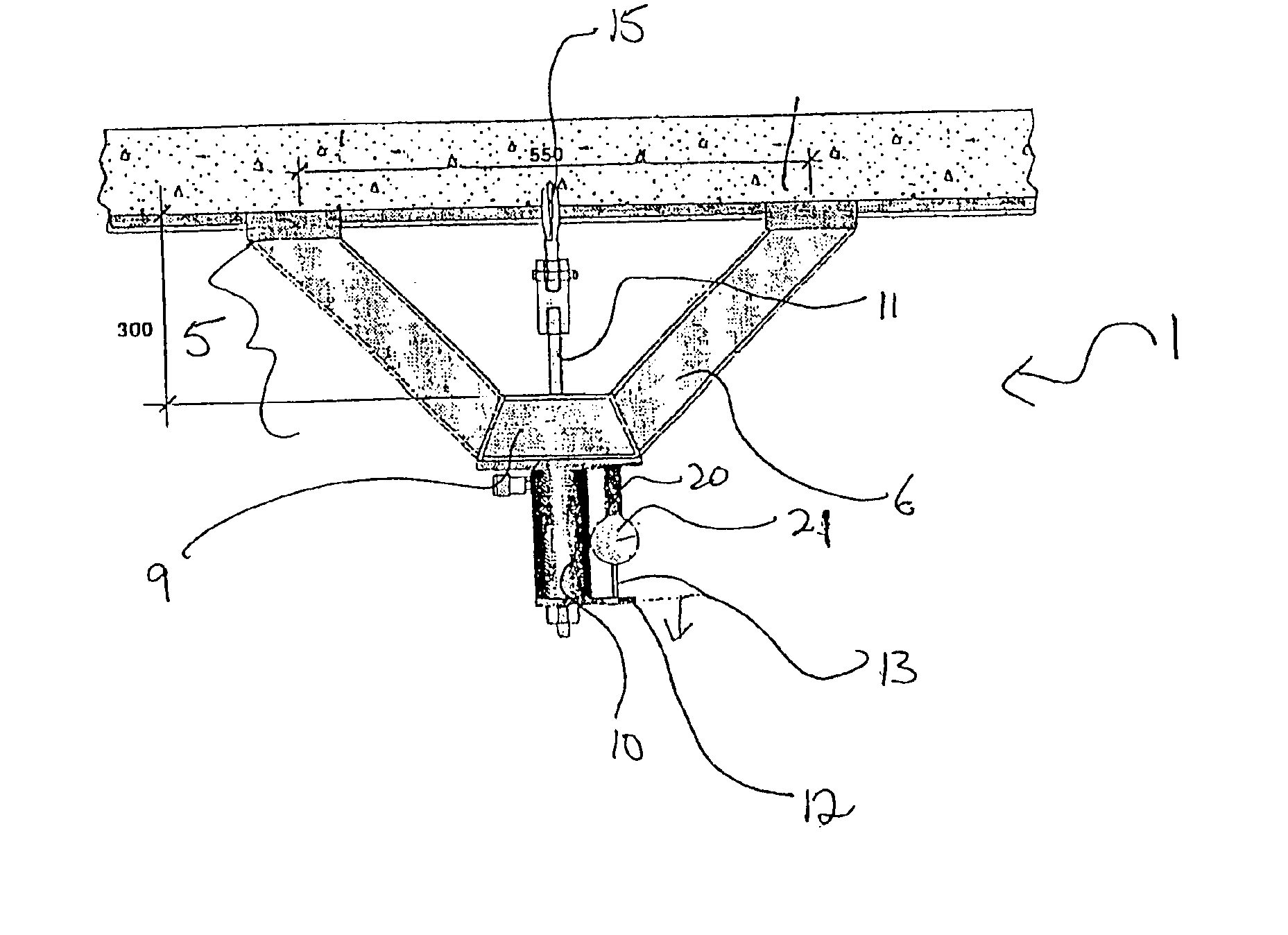
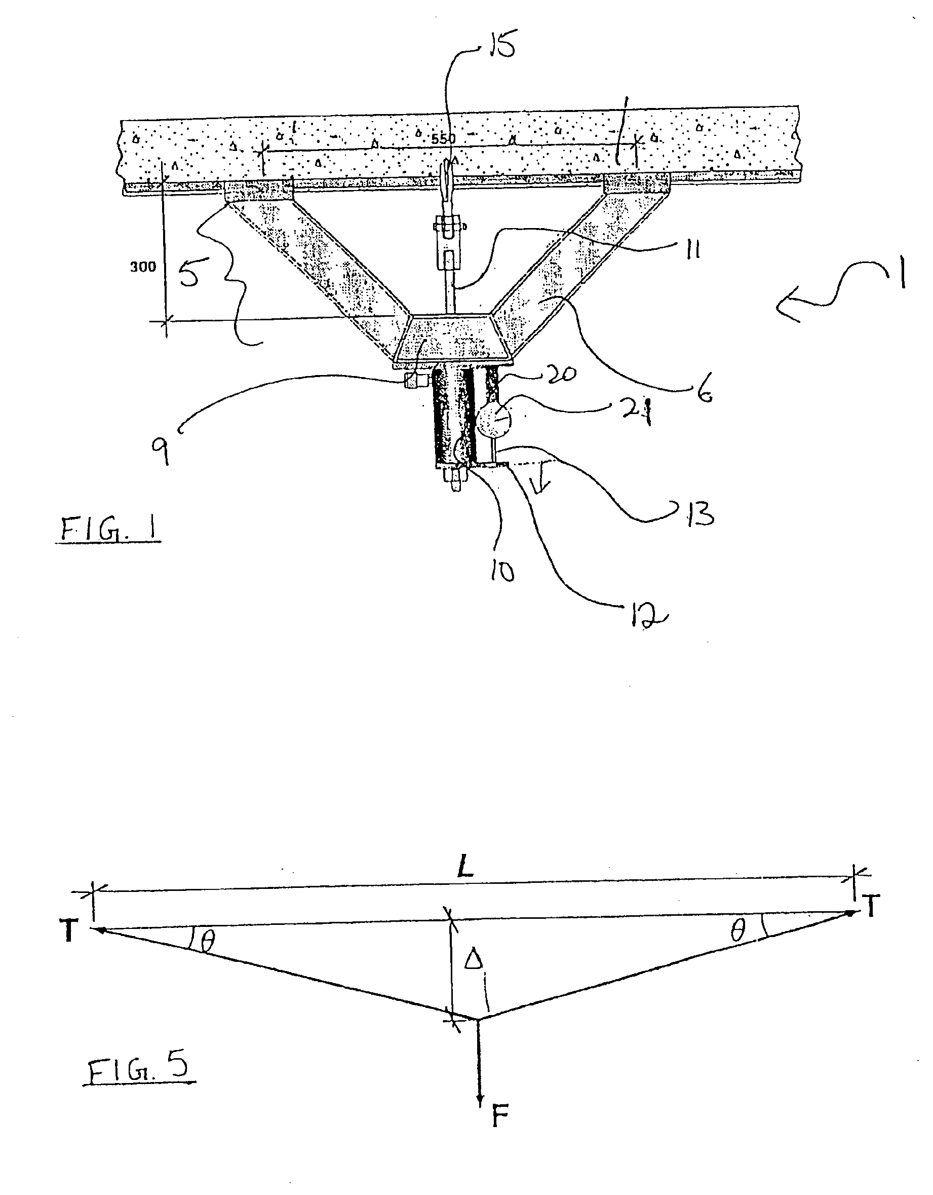
[0022]Referring to FIG. 1, the device 1 for testing the force in a stressed cable contained within a concrete structure includes a frame 5, jack 10, hook 15, and gauge 20.

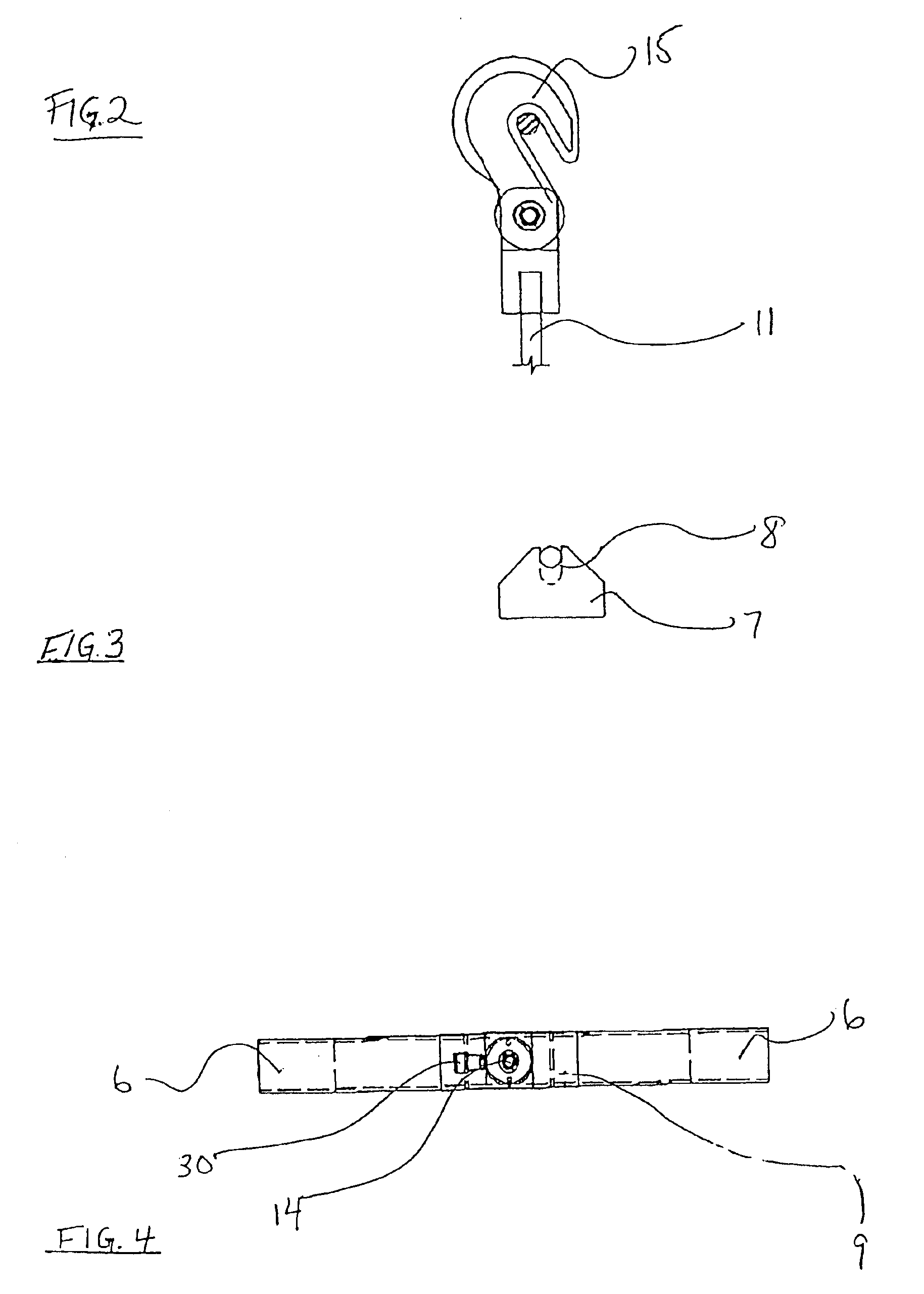
[0023]In a preferred embodiment, the frame 5 is V-shaped with two angled arms 6 attached to a base 9. The arms 6 of the frame 5 extend away from the base 9 and towards the structure. The ends 7 of the arms 6 are angled upward and include a notch 8 configured for attachment to the stressed cable (see FIG. 3). The shape and configuration of the frame 5 are conducive to fitting against a concrete structure while the amount of pre-stress in the stressed cable is measured. In a preferr...


PUM


Abstract

A device and method for testing the tension in a stressed cable of a concrete structure. The device includes a frame and a hydraulic jack mounted onto the frame. The hydraulic jack applies a force to the stressed cable and displaces the stressed cable laterally. A hook or clamp is connected to the hydraulic jack for grasping the stressed cable in order to apply the force thereto, and a dial gauge is mounted onto the frame for measuring the deflection of the stressed cable once the force has been applied. The amount of pre-stress within the stressed cable can be calculated by measuring the amount of deflection caused to the stressed cable by the force of the jack.

Description

BACKGROUND OF THE INVENTION[0001]1. Field of the Invention[0002]The present invention relates to a device and method for testing the tension in stressed cables of concrete structures, particularly the pre-stressing forces in unbonded tendons in post-tensioned concrete structures.[0003]2. Description of the Related Art[0004]Concrete, while capable of carrying a compressive vertical load, does not carry tensile forces well. To help alleviate this problem, during the last twenty years concrete builders have begun to use unbonded tendons in post-tensioned structures. The unbonded tendons consist of steel cables made up of thin wires wrapped around each other and placed in grease-filled sheathing. The unbonded tendons are anchored at their ends and attached to the concrete solely at these end anchors. Over time such stressed cables have been known to deteriorate, corrode and / or break, thereby resulting in unsafe conditions within the structures, the result being the replacement of the ex...

Claims


Application Information

Patent Timeline
IPC IPC(8): G01L5/06G01L5/04
CPCG01L5/06
Inventor GUPTA, PAWAN R.
Owner HALSALL ASSOCS
Why Eureka
Try Eureka