Device for carrying out work in an elevator shaft
- Summary
- Abstract
- Description
- Claims
- Application Information
AI Technical Summary
Benefits of technology
Problems solved by technology
Method used
Image
Examples
Embodiment Construction
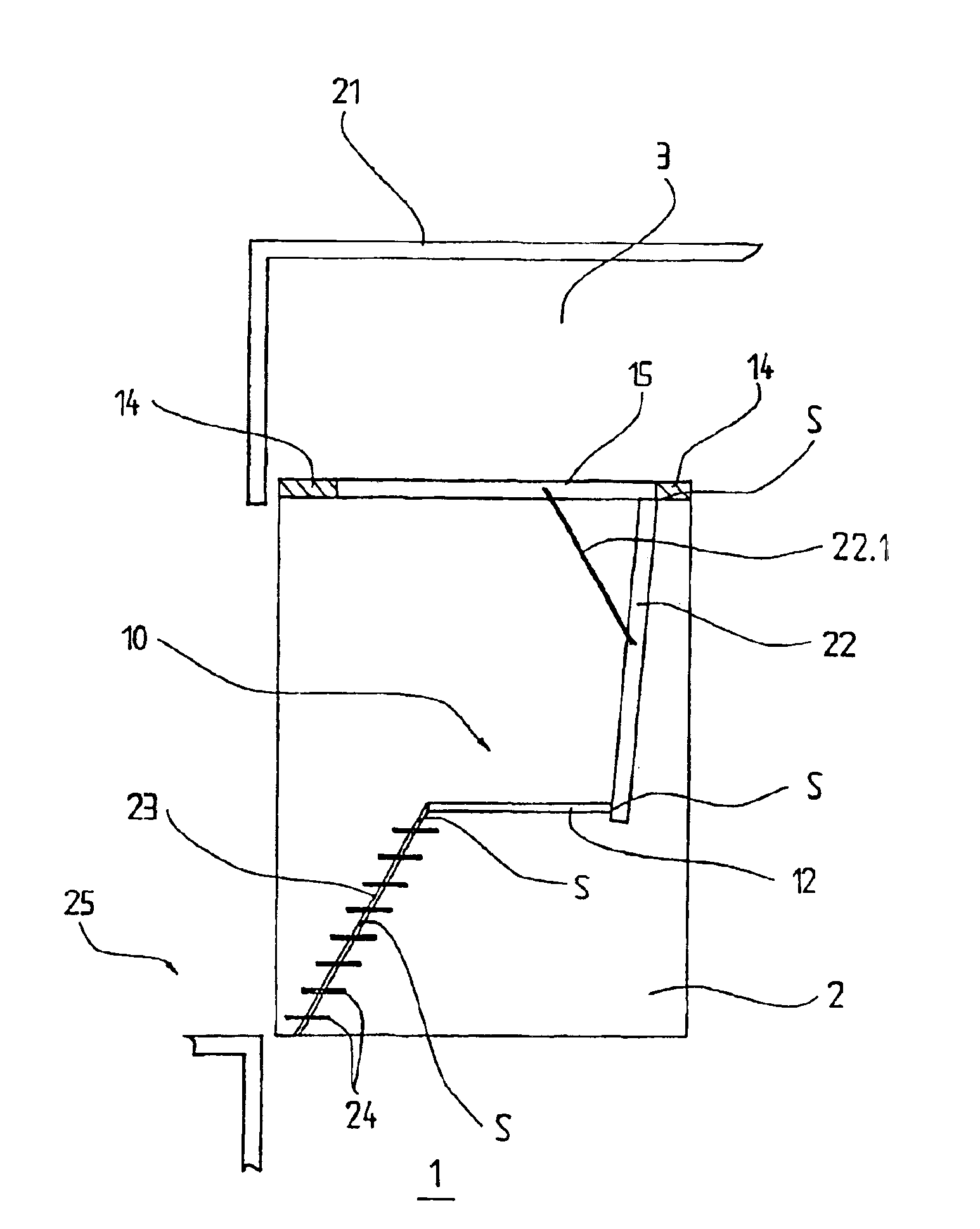
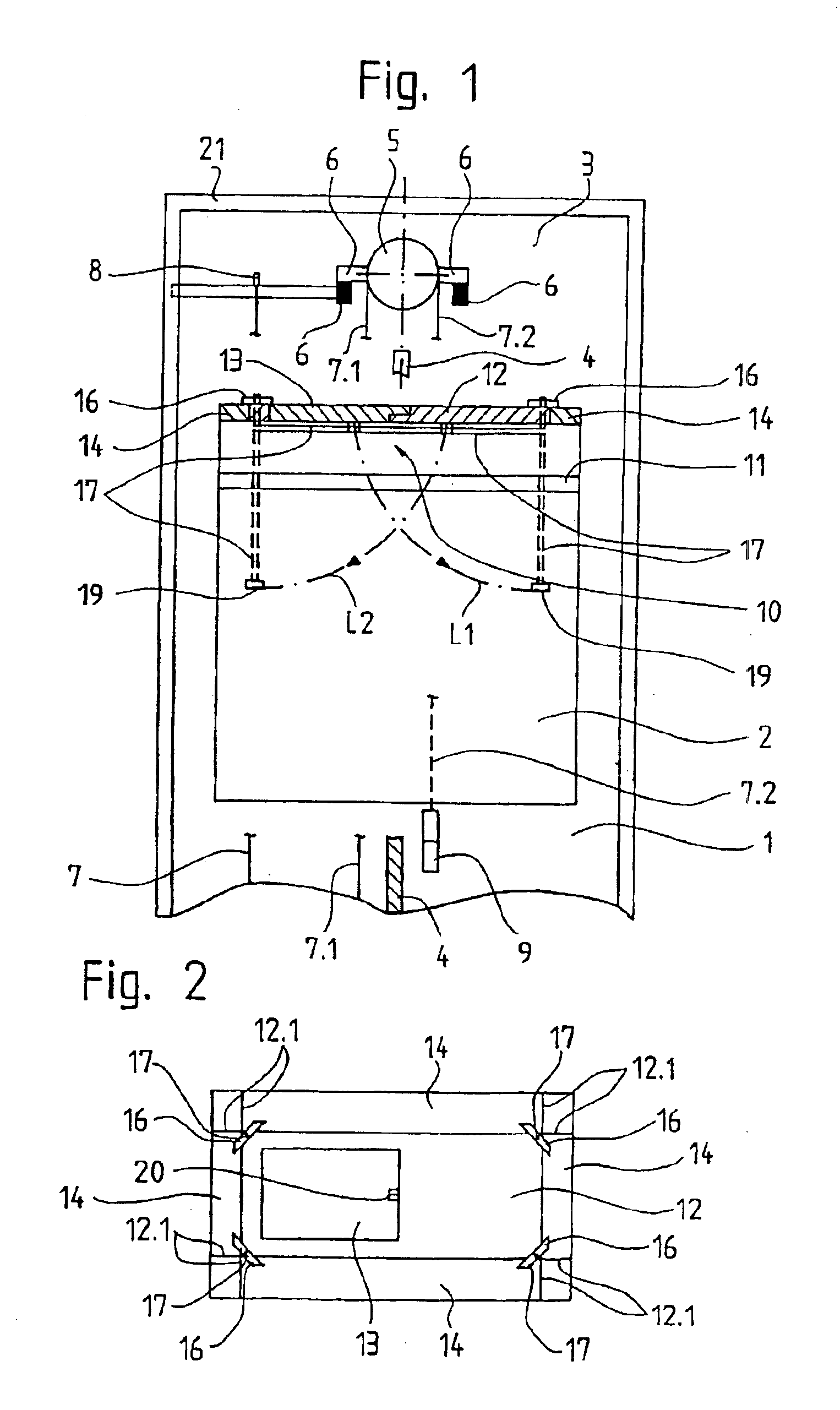
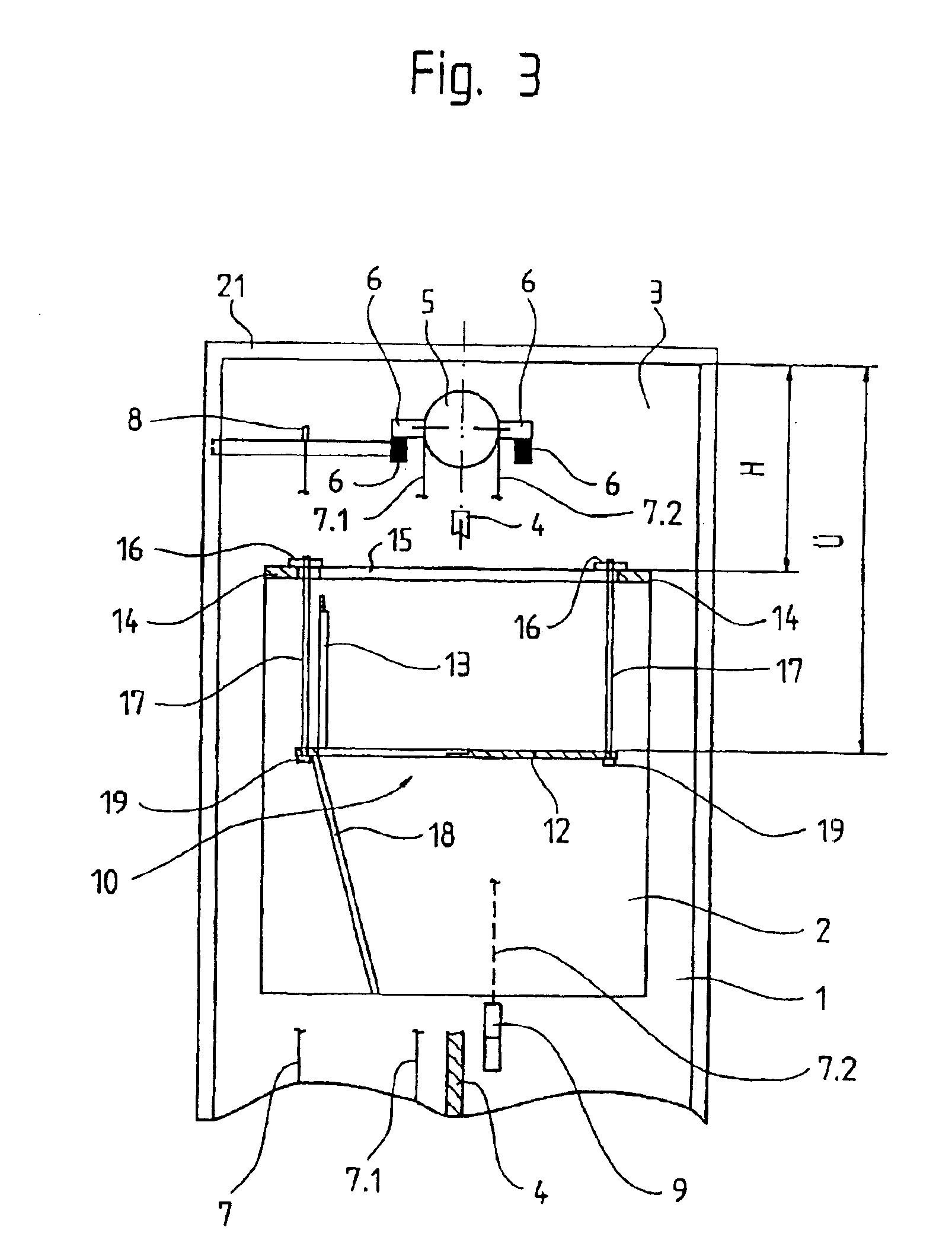
[0015]In FIGS. 1 to 3, 1 indicates an elevator hoistway in which an elevator car 2 can be caused to travel. Located in the hoistway headroom 3 above a guiderail 4 for the elevator car 2 is a traction sheave 5 which is connected to a drive which is not shown. The traction sheave 5 is supported by, for example, a wall bracket 6. The counterweight end of a suspension rope 7, which passes over the traction sheave 5 and has a 2:1 roping arrangement, is indicated by 7.1, and the car end of the suspension rope 7 is indicated by 7.2. On the counterweight side, the suspension rope ends at a first dead-end hitch 8. On the car side, the rope 7.2 passes over a first pulley referred to as an underslung pulley 9, then over a second underslung pulley (not shown), and terminates at a second dead-end hitch which is also not shown. The 2:1 roping arrangement is especially suitable for the machine-room-less elevator layout shown, where the elevator car 2 is carried by the two underslung pulleys 9 and ...
PUM
 Abstract
Description
Claims
Application Information
 - R&D
- Intellectual Property
- Life Sciences
- Materials
- Tech Scout
- Unparalleled Data Quality
- Higher Quality Content
- 60% Fewer Hallucinations
Browse by: Latest US Patents, China's latest patents, Technical Efficacy Thesaurus, Application Domain, Technology Topic, Popular Technical Reports.
© 2025 PatSnap. All rights reserved.Legal|Privacy policy|Modern Slavery Act Transparency Statement|Sitemap|About US| Contact US: help@patsnap.com


