Separating device

a technology of separating device and wedge, which is applied in the direction of lifting device, auxillary member of form/shuttering/falsework, life-saving device, etc., can solve the problems of subsequently jamming of the mechanism, and achieve the effect of reducing the tendency of the drive mechanism for the wedge to jam and less prone to failur

Inactive Publication Date: 2005-04-19
ACTUANT OPERATIONS UK LTD
View PDF8 Cites 3 Cited by
  • Summary
  • Abstract
  • Description
  • Claims
  • Application Information

AI Technical Summary

Benefits of technology

[0017]The device preferably includes a third pin and slot arrangement. The third pin and slot arrangement typically comprises one or more pins that locate into an aperture in the support device. The pin(s) typically pass through a slot in the first plate. The third pin and slot arrangement provides the advantage that the first plate can be held securely against the support device and/or the wedge member during operation of the device. This substantially preven...

Problems solved by technology

A disadvantage with this is that the load of the objects being separated is concentrat...

Method used


Image

  • Separating device
  • Separating device
  • Separating device

Examples


Embodiment Construction

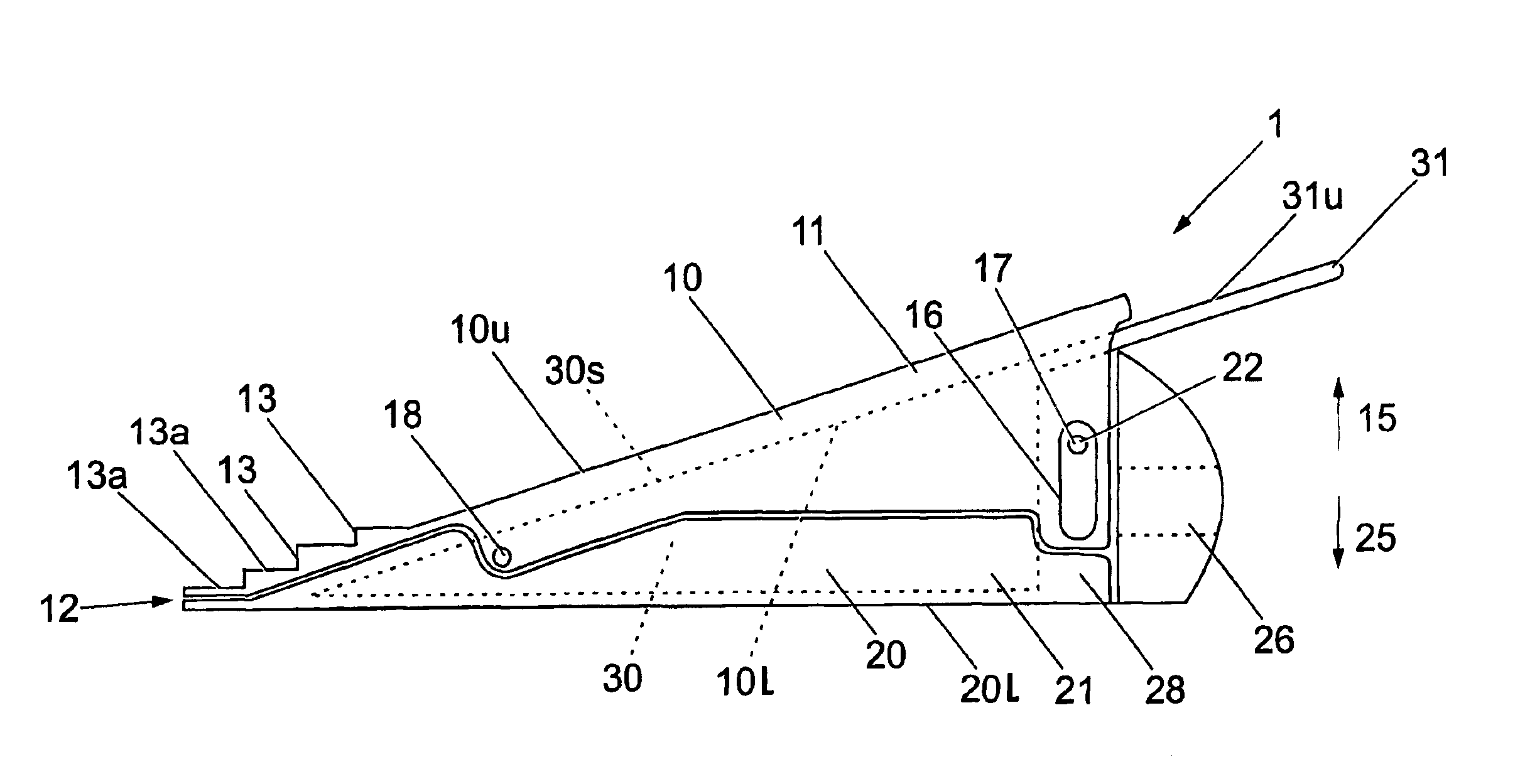
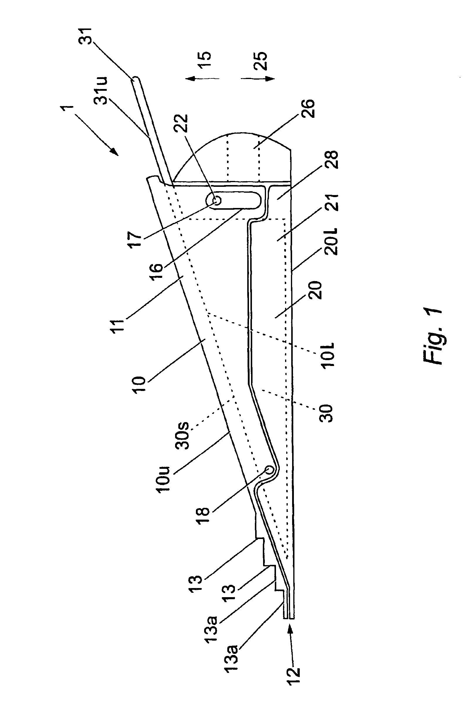
[0026]FIG. 1 shows an exemplary embodiment of a separating device 1 that includes a first or upper plate 10, a second or lower plate 20 and a wedge 30. Use of the terms “upper” and “lower” herein refer to the orientation of the device 1 as shown in FIGS. 1 to 3.

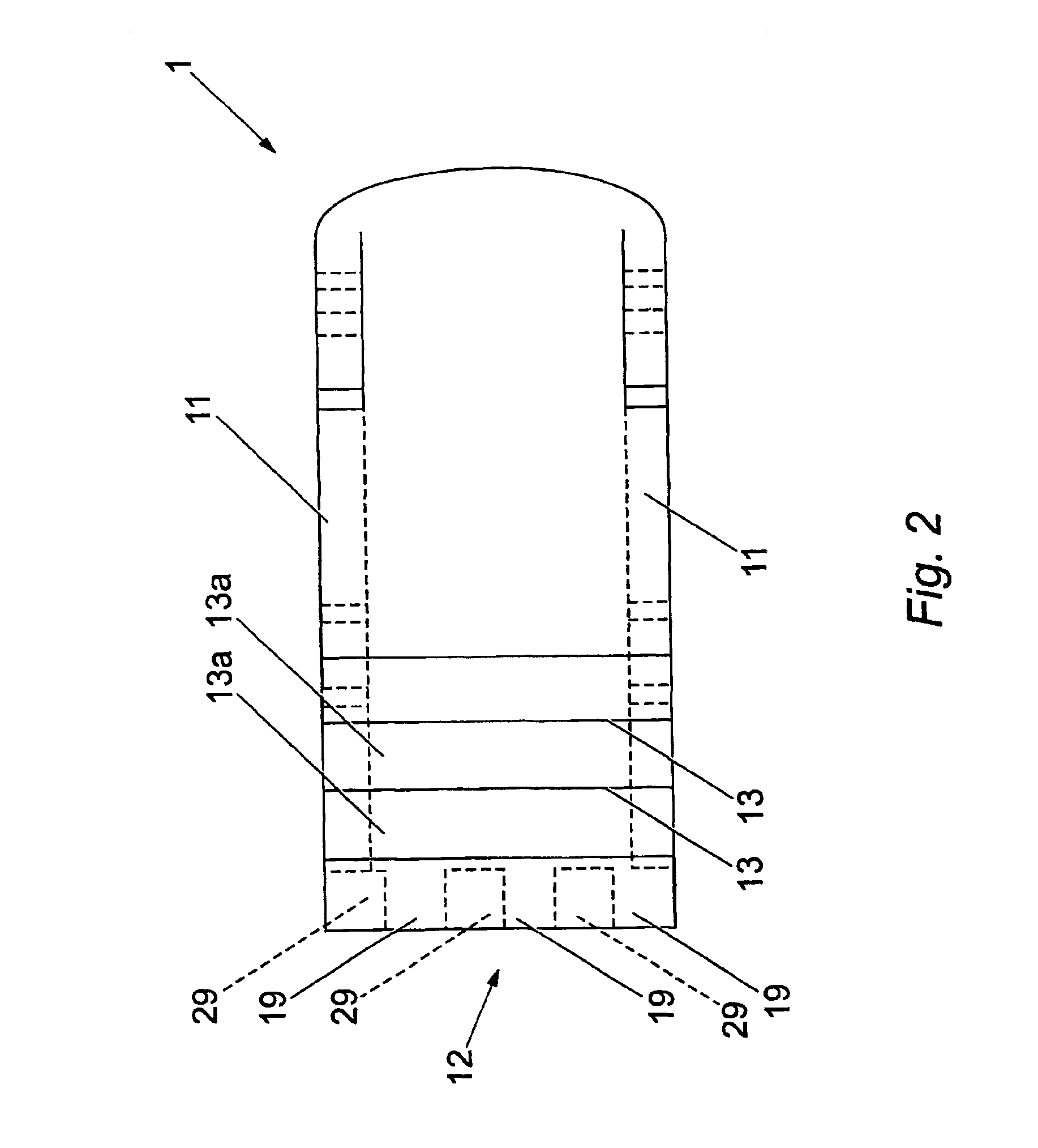
[0027]The upper plate 10 has two sidewalls 11 that extend downwards in a plane perpendicular to an upper surface 10u of the upper plate 10 from opposite edges. The upper plate 10 is normally welded to the sidewalls 11 but may be secured by any conventional means such as counter-sunk bolts or the like, or may be formed as one with the sidewalls 11. Similarly, the lower plate 20 has sidewalls 21 that extend upwards in a plane perpendicular to a lower surface 201 of the lower plate 20 from opposite edges. The edges of sidewalls 11, 21 of the plates 10, 20 can be shaped to interfit with one another to enclose the wedge 30 when the upper plate 10 and the lower plate 20 are brought together (as shown in FIG. 1).

[0028]The sidewalls ...


PUM


Abstract

A separating device that includes a wedge that extends between first and second plates, with at least one of the plates being supported by a support device such as a bar. The support device supports the or each plate while the device is in use so that the plate(s) are substantially prevented from bending or twisting due to the forces applied to the plate(s).

Description

FIELD OF THE INVENTION[0001]The invention relates to a separating device.BACKGROUND OF THE INVENTION[0002]Hydraulic lifting and separating wedges are known. These wedges usually consist of a central wedge-shaped portion located between two external plates. The external plates are located between the objects to be separated or under the object to be lifted, and the wedge is driven forward between the two plates in order to push the plates apart, thereby separating the objects or lifting the object.[0003]It is known to couple the plates by a pin and slot arrangement so that the or each plate moves in only one direction. A disadvantage with this is that the load of the objects being separated is concentrated at a critical point and so the plates tend to bend and the mechanism may subsequently jam.SUMMARY OF THE INVENTION[0004]According to the present invention there is provided a separating device having a wedge member movable between first and second plates to separate the plates, and...

Claims


Application Information

Patent Timeline
IPC IPC(8): A62B3/00
CPCA62B3/005Y10S269/905
Inventor STEPHEN, ROBERTWILKIE, DAVID
Owner ACTUANT OPERATIONS UK LTD
Why Eureka
Try Eureka