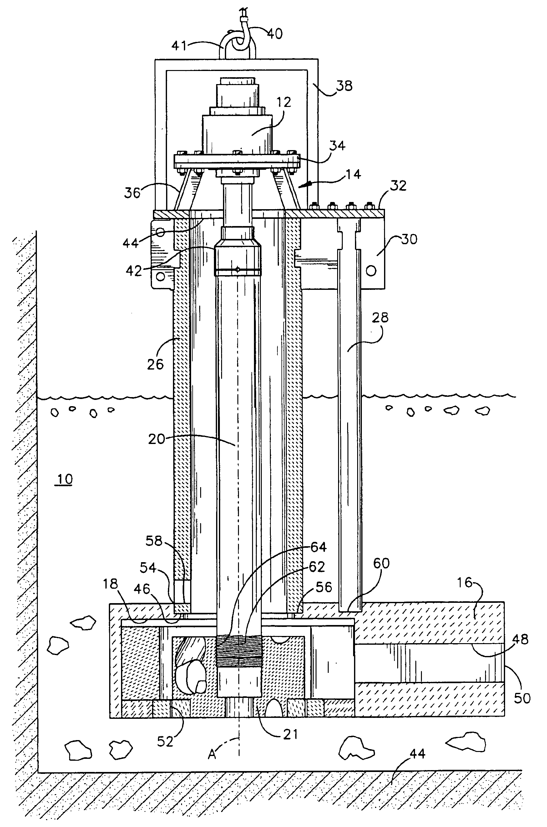
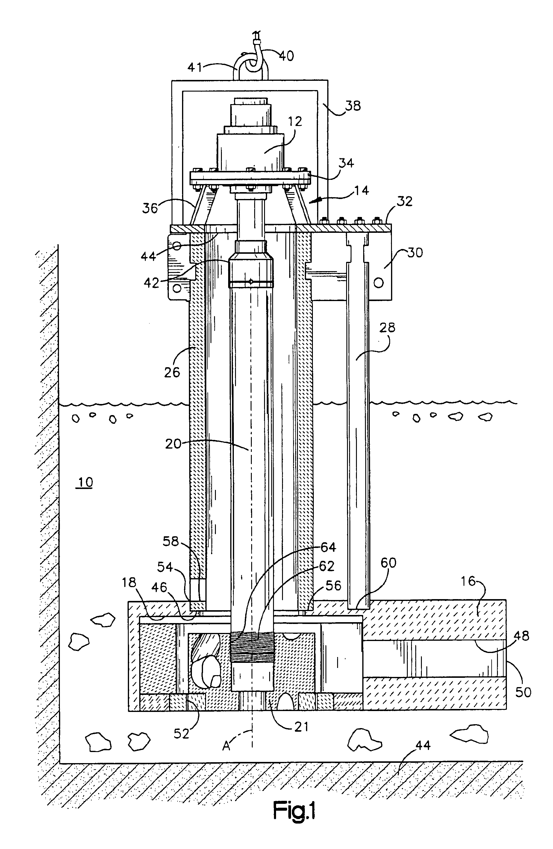
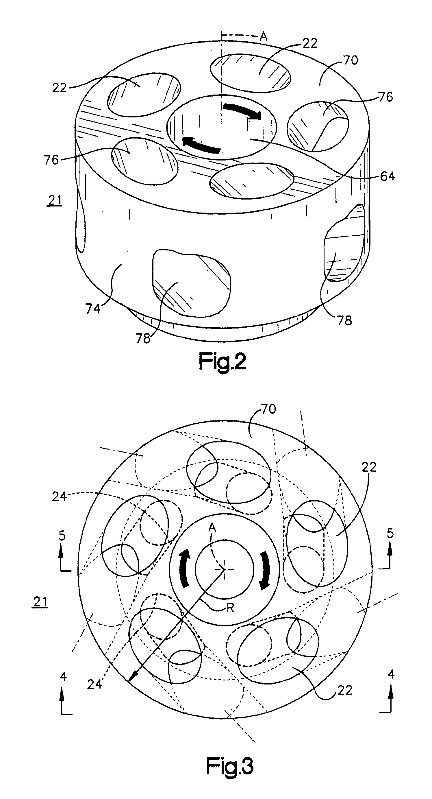
Impeller for molten metal pump with reduced clogging

a technology of impeller and molten metal, which is applied in the direction of liquid fuel engines, marine propulsion, and vessel construction, etc., can solve the problems of clogging of impeller, poor casting of metal, and damage to solid impurities, so as to increase the efficiency of the impeller and prevent clogging

Inactive Publication Date: 2005-04-19
THUT BRUNO H
View PDF36 Cites 107 Cited by
  • Summary
  • Abstract
  • Description
  • Claims
  • Application Information

AI Technical Summary

Benefits of technology

[0009]The present invention is directed to a pump for pumping molten metal with an impeller. One aspect of the invention utilizes an impeller comprising internal molten metal passages which are configured to increase the efficiency of the impeller. The travel of molten metal through the passages is at an

Problems solved by technology

One problem that such pumps encounter is that they may be damaged by solid impurities contained in the molter metal including chunks of refractory brick and metal oxides (e.g. aluminum oxides).
If a piece of hard refractory material becomes jammed in the impeller chamber it may destroy the impeller or shaft, and result in the expense of replacing these components.
Refractory impurities in the molten metal are also a problem since, if not removed, they result in poor castings of the metal and potentially defective parts.
Removing impurities from the molten metal bath is a hazardous process.
Although workers wear protective gear, they may be injured by splatters of metal.
At the least, workers face a difficult task in removing the impurities, which they carry out in a two-step process, spooning the material upwar

Method used


Image

  • Impeller for molten metal pump with reduced clogging
  • Impeller for molten metal pump with reduced clogging
  • Impeller for molten metal pump with reduced clogging

Examples


fourth embodiment

[0097]FIGS. 23-25 show the vaned impeller according to a The vaned impeller includes upper entrance ports or inlets 126 disposed in the first end face 102 in alignment with molten metal entrance ports or inlets 127 of the second end face 104. Upper passages 124a extending from the upper inlets 126 in the upper end face 102 and lower passages 124b extending from the lower inlets 127 in the lower end face 104 lead to the cavities 120 and are also in alignment such that an axis (represented by rod 300 in FIG. 23) can extend into an inlet 126 and passage 124a of upper base 106 through impeller to inlets 127 and passages 124b of lower base 108. The alignment produces generally round openings 320 (best shown in FIG. 24) extending through impeller 100.

fifth embodiment

[0098]FIGS. 26-36 show further embodiments of the present invention in which the impellers are made of a non-metallic, heat resistant material, such as graphite and / or ceramic, suitable for operating in molten metal. In the fifth embodiment, FIGS. 26-28 show an impeller 400 which includes a rotational axis A and first and second end faces 402, 404 extending perpendicular to the central axis A. The first end face 402 is formed by the top surfaces of an upper base 406 of the impeller and the second end face 404 is formed by the bottom surface of a lower base 408 of the impeller (FIG. 28). Both the upper base 406 and the lower base 408 include an opening (409a, 409b respectively), centered about the central axis A. The impeller bases 406, 408 are defined by the volume of material in a radial direction from peripheral edge 425 of each of the openings 409a, 409b to the outer peripheral surface 418 of the impeller 400 and, in a direction along axis A shown in FIG. 28, providing the impell...

sixth embodiment

[0101]Referring to FIGS. 29-31, a sixth embodiment is shown. Impeller 500 includes a rotational axis A and first and second end faces 502, 504 extending perpendicular to the central axis A. The first end face 502 is formed by the top surfaces of an upper base 506 of the impeller and the second end face 504 is formed by the bottom surface of a lower base 508 of the impeller (FIG. 31). Both the upper base 506 and the lower base 508 include an opening (509a, 509b respectively), centered about the central axis A. The impeller bases 506, 508 are defined by the volume of material in a radial direction from peripheral edge 525 of each of the openings 509a, 509b to the outer peripheral surface of the impeller 518 and, in a direction along axis A shown in FIG. 31, providing the impeller bases 506, 508 with a substantially ring-shaped geometry. The impeller bases 506 and 508 include an annular recess 519a, 519b, respectively, in which an annular bearing member 512 resides. The annular bearing...


PUM


Abstract

One aspect of the invention is directed to an impeller made of a non-metallic, heat resistant material, comprising a generally cylindrical shaped body, first and second generally planar end faces and a side wall extending between the first and second faces. A plurality of passages have inlets circumferentially spaced apart from each other on the first face, outlets at the impeller sidewall, and connecting portions extending between the inlets and the outlets transverse to the central axis. Another aspect of the invention is directed to an impeller comprising a central hub portion and first and second impeller bases, including end faces, transverse to a central axis. Vanes extend from the central hub portion between the impeller bases. Cavities are formed between the impeller bases and between adjacent vanes. Molten metal inlets on the end faces for molten metal to reach the cavities. Pumps are also disclosed using the inventive impellers.

Description

RELATED APPLICATIONS[0001]The present application is a continuation-in-part application containing common subject matter with presently pending application Ser. No. 09 / 774,938, which was filed in the United States Patent and Trademark Office on Jan. 31, 2001, now U.S. Pat. No. 6,524,066.FIELD OF THE INVENTION[0002]This invention relates to impellers and to pumps for pumping molten metal which employ the impellers.BACKGROUND OF THE INVENTION[0003]Pumps used for pumping molten metal typically include a motor carried by a motor mount, a shaft connected to the motor at one end, and an impeller connected to the other end of the shaft. Such pumps may also include a base with an impeller chamber, the impeller being rotatable in the impeller chamber. Support members extend between the motor mount and the base and may include a shaft sleeve surrounding the shaft, support posts, and a tubular riser. An optional volute member may be employed in the impeller chamber Pumps are designed with shaf...

Claims


Application Information

Patent Timeline
IPC IPC(8): F04D7/00F04D29/04F04D7/06F04D29/22F04D29/18
CPCF04D7/065F04D29/0405F04D29/2288F04D29/2255F04D29/22F04D29/043
Inventor THUT, BRUNO H.
Owner THUT BRUNO H
Why Eureka
Try Eureka