Amphibious vehicle comprising an improved decoupler

a technology of decoupler and amphibious vehicle, which is applied in the direction of couplings, vessel construction, and propellers, etc., can solve the problems of reducing the available space for external drive shaft decouplers, prohibitively expensive dedicated transmissions, and increasing the cost of decouplings, so as to achieve the effect of reducing costs

Inactive Publication Date: 2005-04-19
GIBBS TECH
View PDF14 Cites 26 Cited by
  • Summary
  • Abstract
  • Description
  • Claims
  • Application Information

AI Technical Summary

Benefits of technology

[0014]This arrangement has the added advantage that a known synchromesh device from a conventional gearbox can be adopted for use in the decoupler. This enables the synchroniser device of the decoupler to be manufactured using commercially available components at much lower cost than would be the case if the components were to be purpose designed and manufactured.

Problems solved by technology

For amphibious vehicles, which are used in specialized applications and are produced in relatively low volumes, a dedicated transmission would be prohibitively expensive.
A problem with known external drive shaft decouplers is the amount of extra space they require.
This is a particular problem in amphibious vehicles in which the wheels are designed to retract upwardly and inboard of the vehicle for use of the vehicle in water.
In such vehicles the provision of wheel retraction systems and specialized suspension systems reduces the available space for external drive shaft decouplers.
A further problem which arises is the need to synchronise the speeds of the input and output means of the decoupler when drive is being coupled.
This problem arises, for example, when the vehicle is preparing to leave the water with the wheels deployed.
A similar problem arises when the vehicle enters the water, when it is desirable to couple drive to the marine propulsion system whilst drive to the road wheels is maintained.

Method used


Image

  • Amphibious vehicle comprising an improved decoupler
  • Amphibious vehicle comprising an improved decoupler
  • Amphibious vehicle comprising an improved decoupler

Examples


Embodiment Construction

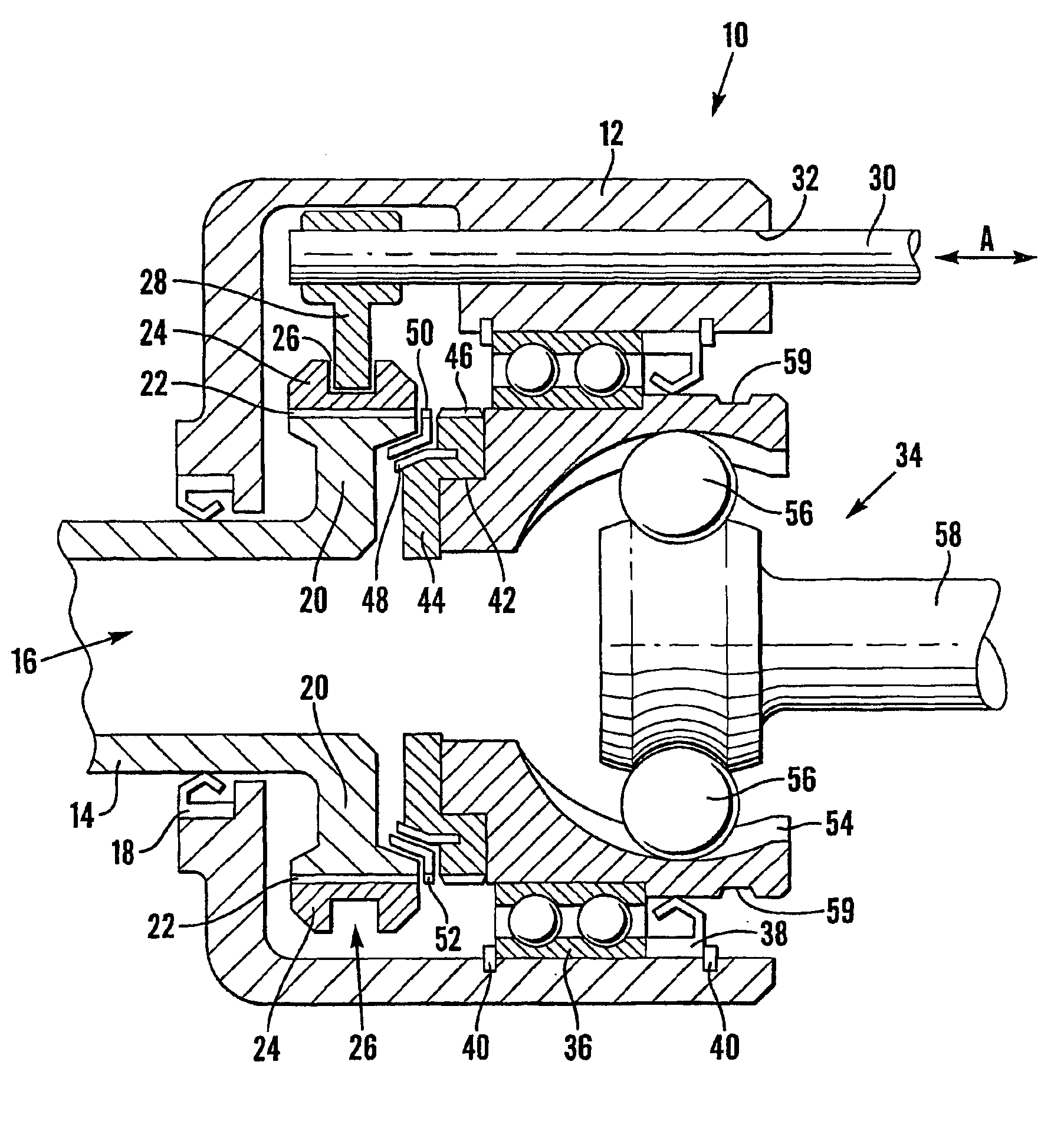
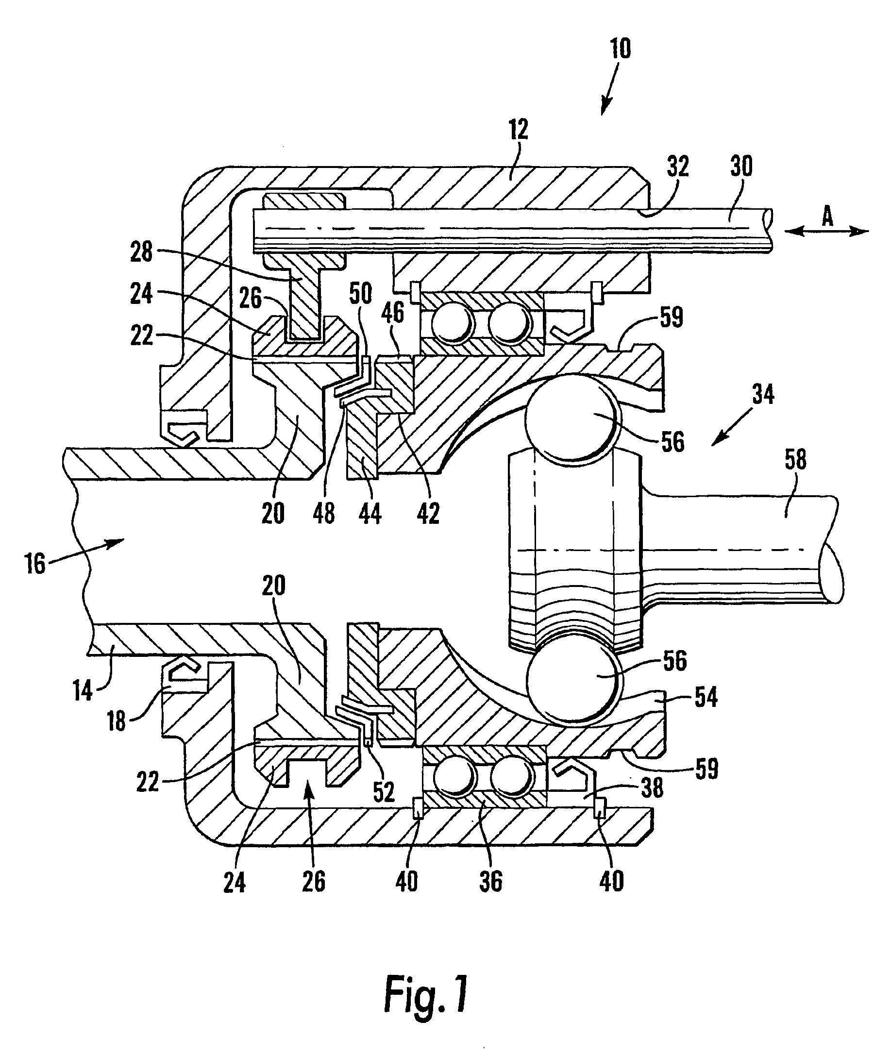
[0022]Referring firstly to FIG. 1, a decoupler incorporating a constant velocity CV joint is indicated generally at 10. The decoupler 10 is of the form of an integrated unit, which is housed in a casing 12. A driving shaft 14, which may be from the output stage of a gearbox or from a differential (not shown), enters the casing 12 through a circular aperture 16 to the left hand side of the casing 12 (as viewed), and is free to rotate within the casing. An oil seal 18 seals between the driving shaft 14 and the aperture 16. The driving shaft 14 comprises an input of the decoupler 10.

[0023]The driving shaft 14 terminates inside the casing 12 in a flange 20, the periphery of which is splined 22. A drive ring 24, which is correspondingly internally splined, is in permanent driving engagement with the spline 22 and rotates with the driving shaft 14. A circumferential slot 26 is provided in the periphery of the drive ring 24, and a selector arm 28 locates in the slot 26. A rod 30, which is ...


PUM


Abstract

A decoupler for coupling/decoupling drive between a power train output and road wheels or marine drive means in an amphibious vehicle, is integrated with a constant velocity joint, saving space, weight, and cost for low production volumes, and simplifying mounting arrangements. Power train output shaft enters casing through aperture, and terminates in a flange with splines. Baulk ring and synchrocone provide synchromesh action between drive ring and driven CV joint cap. Rod is attached to selector arm, located in slot, allowing coupling and decoupling by an external control, which may be assisted by a pneumatic or hydraulic cylinder. The synchromesh parts may be sourced from truck gearboxes. CV joint is mounted in bearings, and may be a Rzeppa type. Groove allows fitment of a conventional dust gaiter.

Description

BACKGROUND OF THE INVENTION[0001]The present invention relates to an amphibious vehicle having a decoupler for coupling / decoupling a drive shaft of the vehicle, and more particularly to an amphibious vehicle having a drive-shaft decoupler for engaging and disengaging a drive shaft which driveably connects an output from a power train of the vehicle with the wheels or marine propulsion system of the vehicle.[0002]It has been found convenient to drive the marine propulsion systems of an amphibious vehicle through the transmission by which the wheels are also driven. With this arrangement it is necessary to disengage the drive to the wheels while the drive to the marine propulsion is engaged when the amphibious vehicle is in water mode. It is also desirable to be able to decouple and couple the drive to the wheels and marine propulsion system independently of one another as the vehicle makes the transition between land and marine modes of travel.[0003]In the case of a transmission whic...

Claims


Application Information

Patent Timeline
Patent Type & Authority Patents(United States)
IPC IPC(8): B60F3/00F16D23/06F16D3/221F16D47/00F16D3/16F16D23/02F16D23/04B60K17/02B60F1/00F16D3/22F16D11/10
CPCB60F3/0007F16D3/221F16D47/00F16D23/06F16D23/04F16D3/223F16D2003/22326B60F3/00
Inventor ROYCROFT, TERENCE JAMES
Owner GIBBS TECH
Why Eureka
Try Eureka