Balloon catheter with stent securement means

a balloon catheter and stent technology, applied in the field of assembly methods, can solve the problems of inability the stent can slip and dislocate from its desired position, and the balloon can not be overextended to provide the pressure needed, so as to facilitate the delivery of the balloon catheter and reduce the diameter of the delivery

Inactive Publication Date: 2005-04-19
E2INTERACTIVE INC D B A E2INTERACTIVE
View PDF106 Cites 113 Cited by
  • Summary
  • Abstract
  • Description
  • Claims
  • Application Information

AI Technical Summary

Benefits of technology

[0015]The present invention is an assembly for delivery and deployment of an inflation expandable stent within a vessel. The assembly comprises a catheter, an expandable balloon mounted on the catheter, a stent securement means mounted on the catheter beneath or within the balloon, and a stent mounted on the balloon. The catheter has proximal and distal ends. The stent is inflation expandable from a delivery diameter to a deployment diameter. The delivery diameter is reduced from the deployment diameter for conforming the stent to the catheter. The stent, in its delivery diameter, is coaxially mounted on the catheter near the catheter distal end. The expandable balloon is coaxially mounted on the catheter axially within the stent. The balloon is designed and adapted for expansion of the stent from the delivery diameter to the deployment diameter upon application of fluid deployment pressure to the balloon. The securement means may be corrugated tubing mounted and adhered coaxially onto the catheter and situated between the balloon and the catheter itself. Alternatively, the securement means may be an expandable tube component mounted on the catheter. The expandable tube component is coaxially mounted on the catheter, axially within the expandable balloon. The expandable tube component is designed and adapted for fluid expansion to provide a securement pressure to the stent in the delivery diameter to maintain the stent in position on the catheter during delivery to the deployment site. The expandable tube component is sized and constructed to be fluid expandable to no more than the delivery diameter. The expandable tube component or corrugated tube is essentially equal in length to the stent and the stent is positioned on the assembly essentially coextensive with the tube component. When the stent is crimped and loaded onto the balloon, the balloon is situated therefore between the stent and the securement means. The securement means is preferably essentially equal to the length of the stent and the stent is positioned on the assembly essentially co-extensive with the tube component. The present invention is particularly directed to improved arrangements for releasably attaching the stent to the catheter to facilitate delivery thereof. Generally, the stent is held in place upon the catheter by means of an enlarged body carried by the catheter shaft within the balloon to which the stent and the balloon are fitted, as by crimping. The securement means on the catheter effectively holds the stent in place, takes up the slack due to recoil and protects the balloon material from being damaged during crimping.

Problems solved by technology

During delivery, the stent can thus tend to slip and dislocate from its desired position on the catheter or even become separate from the catheter, requiring further intervention by the physician.
Further, there is a possibility of damaging the balloon during the stent crimping as a result of pinching the balloon material between the metal stent and any metal (or protruding object) on the inner guide lumen (e.g. marker bands).
The expandable tube component is designed and constructed to be expandable to no more than is necessary to compensate for recoil crimping and is incapable of overexpanding to provide the pressure needed to fully expand the stent to its deployment position.
However, none of these references show, suggest or render obvious an inner balloon, in conjunction with an outer deployment inflatable balloon, to provide securement pressure to a compressed stent during delivery to a site within a body vessel.

Method used


Image

  • Balloon catheter with stent securement means
  • Balloon catheter with stent securement means
  • Balloon catheter with stent securement means

Examples


Embodiment Construction

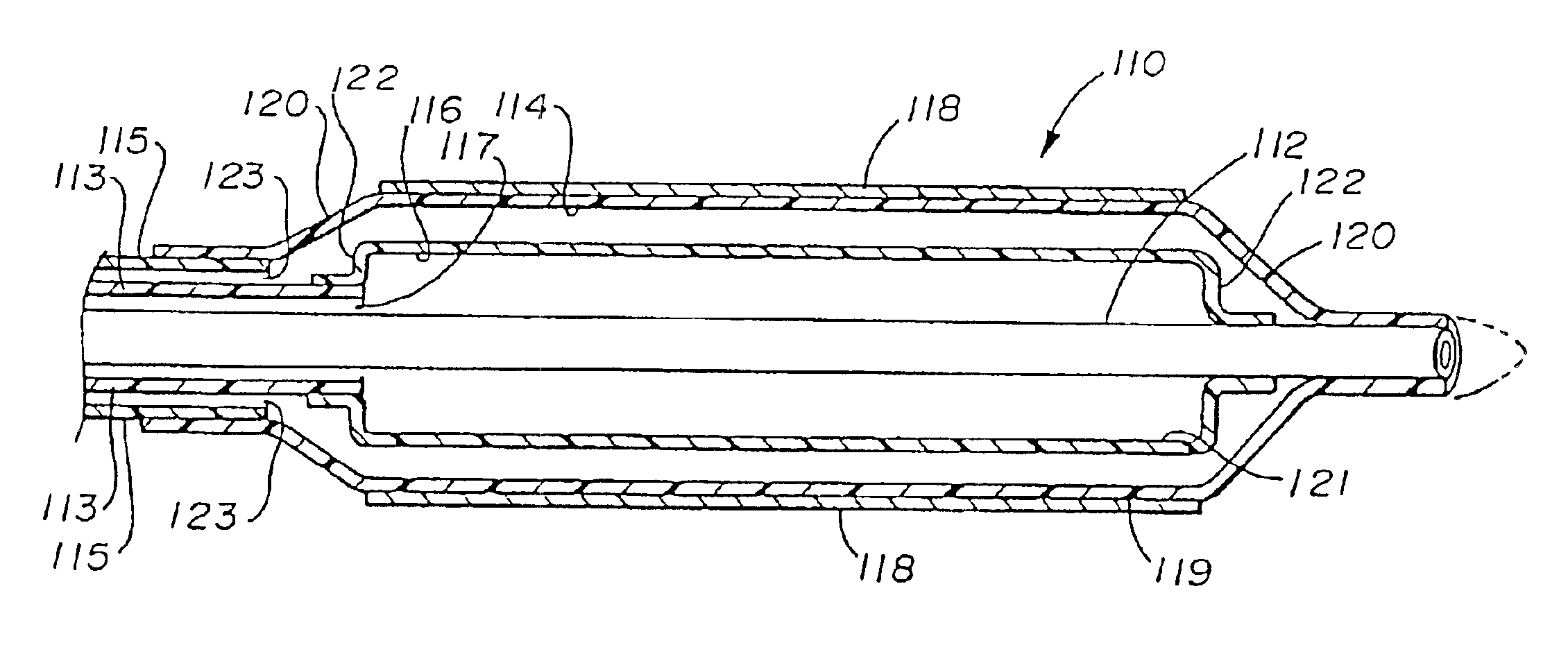
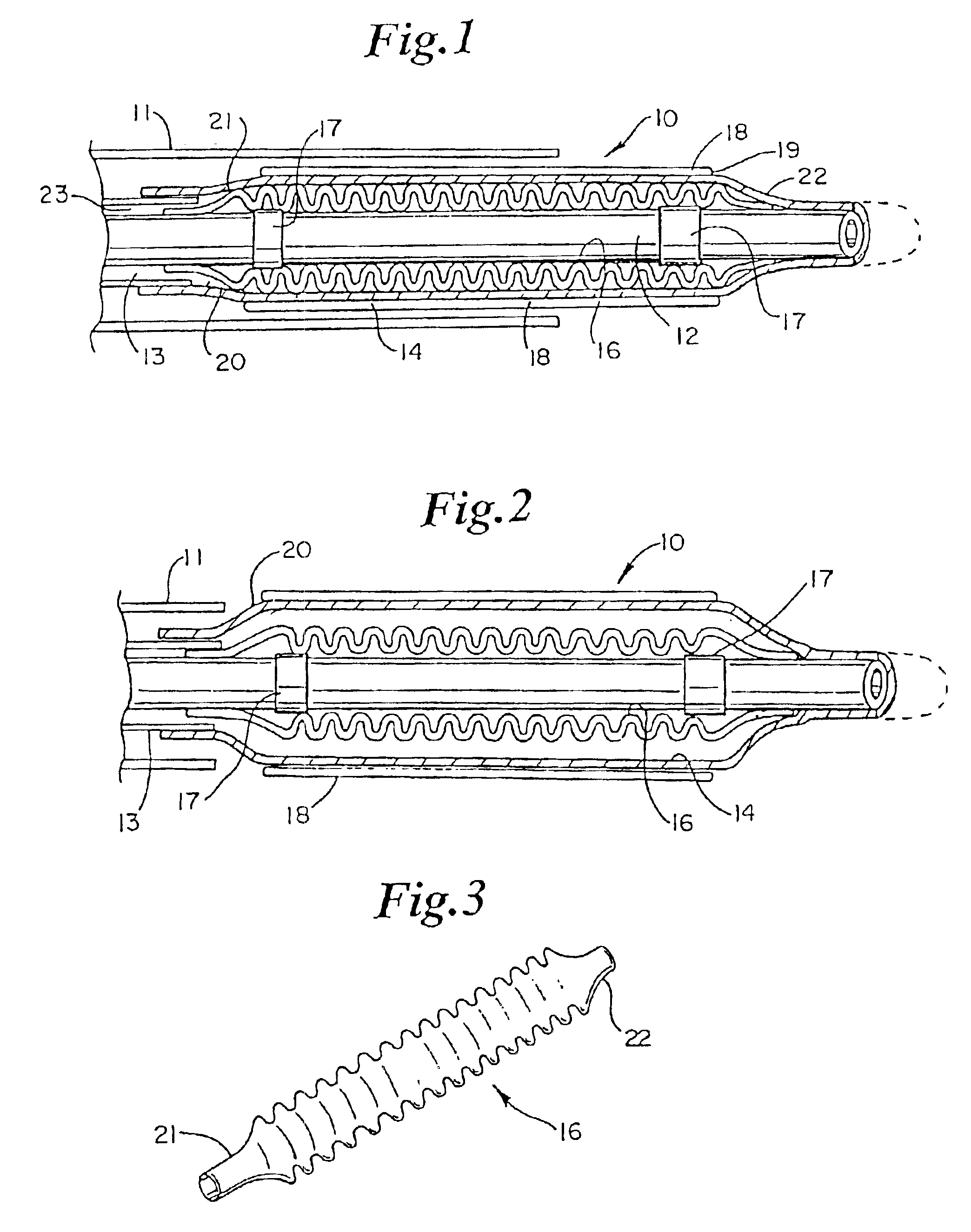
[0027]FIGS. 1 and 2 illustrate a side profile section showing an inflation expandable stent delivery and deployment assembly, generally designated 10. Assembly 10 includes a catheter comprised of inner shaft 12 and outer shaft 13 of the coaxial type and an optional retractable delivery shaft 11 (typically called a guide catheter, shown retracted in FIG. 2), an inflation expandable balloon 14, a corrugated / ribbed stent securement device 16, optional marker bands 17 and an inflation expandable stent 18. Any conventional type of catheter may be used, such as a catheter of the type generally used for PTA or PTCA angioplasty procedures, for prostate therapy, and TTS endoscopic catheters for gastrointestinal use. However, coaxial types as show are most preferred. The particular catheters 12 and 13 shown are formed of a biocompatible and hydrophilic compatible material, such as a lubricous polyimide or poly ethylene. Other suitable materials for the catheters 12 and13 include nylons, ureth...


PUM


Abstract

An assembly for delivery and deployment of an inflation expandable stent within a vessel is comprised of a catheter, an inflation expandable stent, an expandable balloon, and a securement means such as a corrugated tube component or an expandable tube component. The tube component is mounted on the inner shaft beneath the balloon and provides increased securement to the stent in a reduced delivery diameter to maintain the stent on the catheter during delivery to the deployment site. The tube component is adhered to the inner shaft and has a plurality of ribs or is fluid expandable to no more than the delivery diameter and may be comprised of more than one separately inflatable pouch expandable to provide the stent with a substrate seat with increased friction and to decrease the slack in stent recoil crimping. The assembly is used in a method for delivering and deploying a stent, and also adds safety when loading/crimping the stent onto a balloon.

Description

REFERENCES TO CO-PENDING APPLICATIONS[0001]This application is continuation of U.S. application Ser. No. 09 / 727,401, filed Nov. 30, 2000, now U.S. Pat. No. 6,419,685 which is a continuation of U.S. application Ser. No. 09 / 386,758, filed Aug. 31, 1999, now U.S. Pat. No. 6,159,227 which is a continuation of U.S. application Ser. No. 08 / 916,610, filed Aug. 22, 1997, now U.S. Pat. No. 6,123,712, which issued Sep. 26, 2000, which is a continuation-in-part of co-pending U.S. application Ser. No. 08 / 697,453, filed Aug. 23, 1996, now abandoned all of which are herein incorporated by reference in their entirety.BACKGROUND OF THE INVENTION[0002]1. Field of the Invention[0003]This invention relates to an assembly method for delivering and deploying an inflation expandable stent particularly within a lumen of a body vessel. More specifically, this invention relates to the provision of a securement component positioned over the inner catheter, and beneath a balloon and a loaded stent, to maintai...

Claims


Application Information

Patent Timeline
Patent Type & Authority Patents(United States)
IPC IPC(8): A61F2/06A61M29/00A61F2/84A61M25/10
CPCA61F2/95A61F2/958A61M25/1011A61F2002/9522A61F2002/9586A61M2025/1093A61M25/1018A61M2025/1013A61M2025/1063A61M2025/1079A61M25/10184A61F2/9522A61M25/104
Inventor DI CAPRIO, FERNANDONORDIN, STANLEY A.ELLIS, LOUIS G.DUSBABEK, ANDREW J.
Owner E2INTERACTIVE INC D B A E2INTERACTIVE
Why Eureka
Try Eureka