Explosive destruction system for disposal of chemical munitions

a technology of explosive destruction and chemical warfare, which is applied in the direction of liquid chemical processes, explosives, cellulosic plastic layered products, etc., can solve the problems of not being intended to be used for safe detonation and chemical treatment of explosively configured chemical warfare munitions, and none of the devices are designed for purposeful detonation and other problems to achieve the effect of facilitating the neutralization of toxic chemicals

Inactive Publication Date: 2005-04-19
ARMY US SECRECTARY OF THE
View PDF11 Cites 26 Cited by
  • Summary
  • Abstract
  • Description
  • Claims
  • Application Information

AI Technical Summary

Benefits of technology

[0015]It is still another object of the present invention to provide a means for neutralizing or detoxifying any toxic chemicals contained within said vessel.
[0016]It is yet another object of the present invention to provide a means for heating said containment vessel to facilitate the neutralization of toxic chemicals therein.

Problems solved by technology

All of these devices are intended to provide a safe means for transport and / or storage of an explosive, but none are designed for purposeful detonation in order to destroy the explosive, and none are gas-tight or otherwise designed to treat toxic or hazardous chemical payloads.
However, these devices are not intended to be used for the safe detonation and chemical treatment of explosively configured chemical warfare munitions.
This device is not intended to be readily mobile, is not equipped for chemical neutralization, nor is it gas-tight so that it can safely contain toxic chemical warfare agents and byproducts.
Here again, these devices are intended to explosively work or harden a workpiece, are not intended to access the interior of the workpiece or otherwise destroy it, and are not gas-tight or otherwise suitable for disposal of chemical warfare munitions.

Method used


Image

  • Explosive destruction system for disposal of chemical munitions
  • Explosive destruction system for disposal of chemical munitions
  • Explosive destruction system for disposal of chemical munitions

Examples


Embodiment Construction

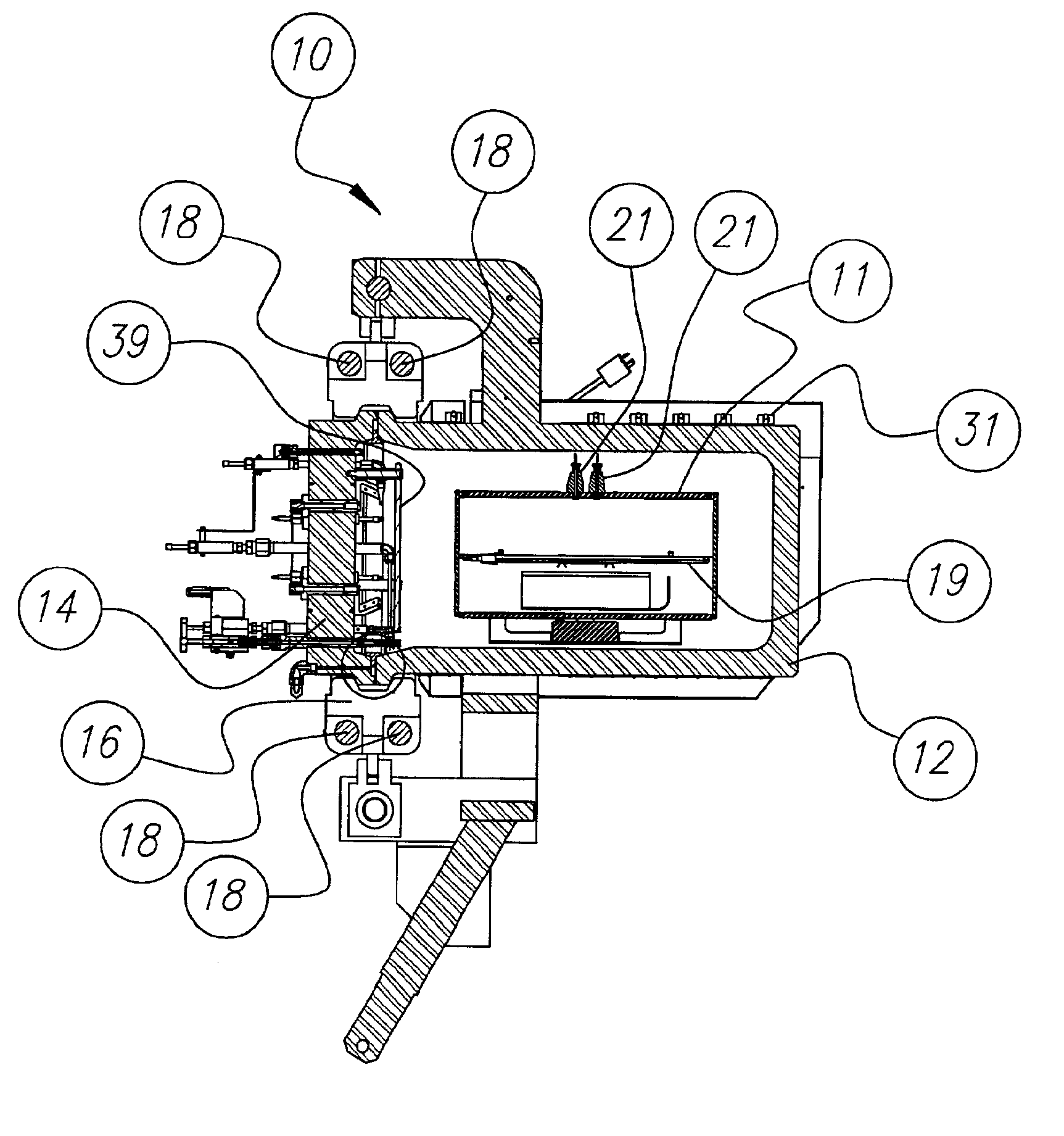
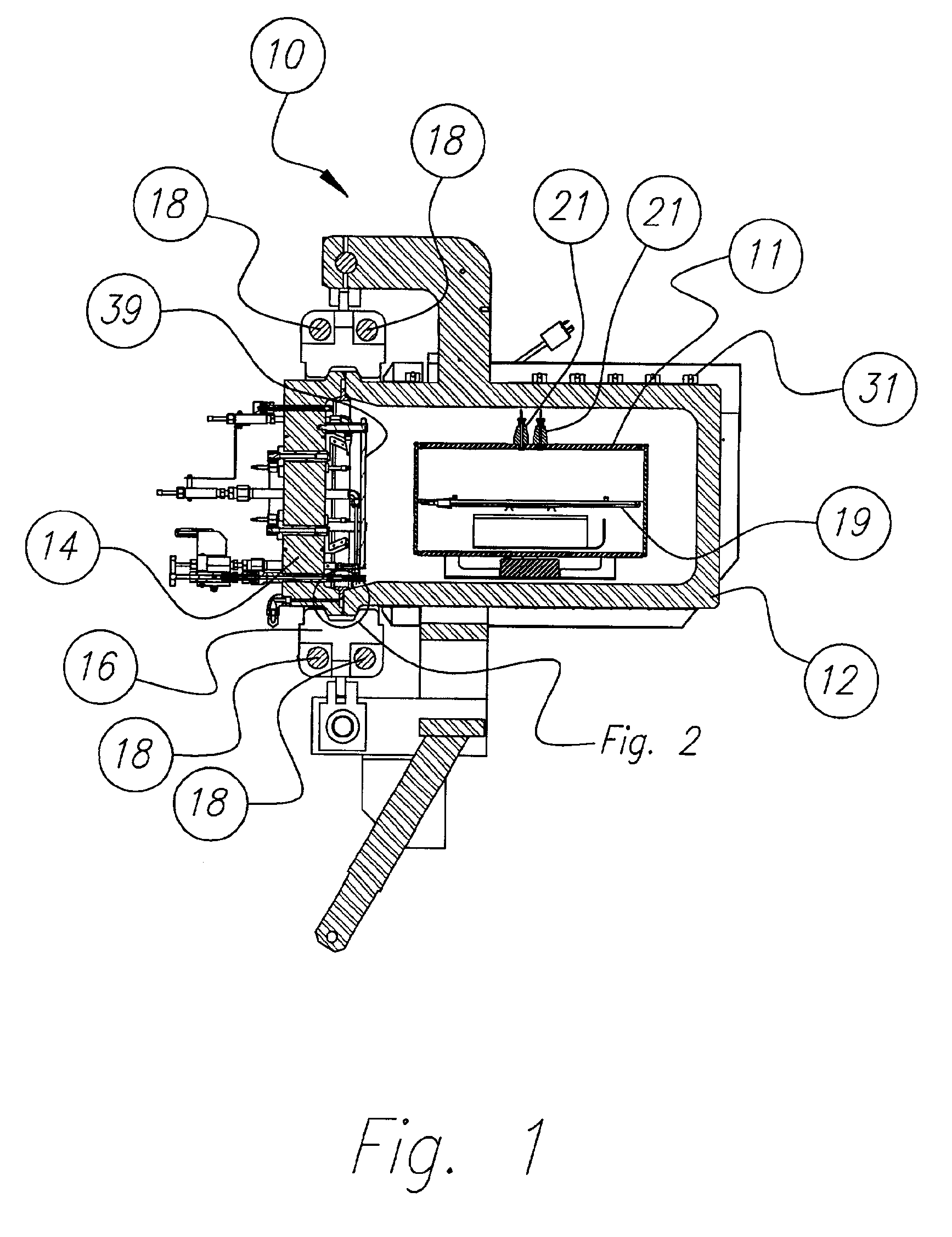
[0034]Referring now to the drawings, like reference numerals represent identical or corresponding parts throughout the several views.

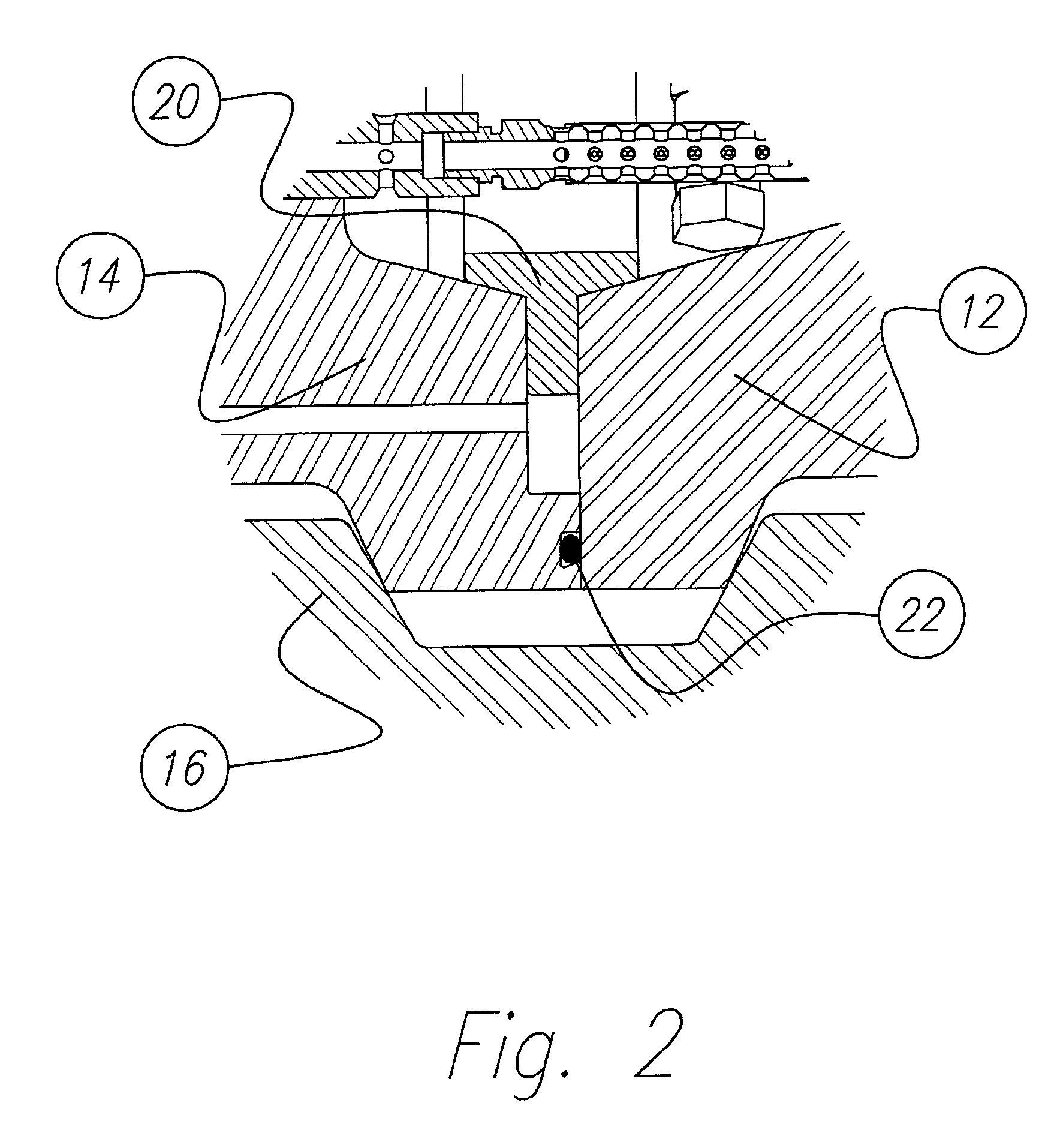
[0035]Turning now to FIG. 1, a longitudinal sectional view of the explosive destructive system 10 is shown. The system comprises a cylindrical containment vessel 12 having a hinged sealable door 14. In a preferred embodiment of the invention, both vessel 12 and door 14 are fabricated from 316 stainless steel forgings. Of course, the size of the vessel 12 will vary according the amount of explosive material the user is required to contain. For example, a vessel 12 designed to contain at least 500 detonations of about 1.0 pound of explosive (TNT equivalent) comprises about a 6.5 cubic foot cylindrical vessel having an inside chamber of 20 inches with 2-inch thick walls. The hinged door 14 is the same diameter as the vessel 12, allowing easy access for inserting munitions and removing debris. In this embodiment, the door 14 is secured with a large, two-pi...


PUM

PropertyMeasurementUnit
pressureaaaaaaaaaa
thickaaaaaaaaaa
lengthsaaaaaaaaaa

Abstract

An explosive destruction system and method for safely destroying explosively configured chemical munitions. The system comprises a sealable, gas-tight explosive containment vessel, a fragment suppression system positioned in said vessel, and shaped charge means for accessing the interior of the munition when the munition is placed within the vessel and fragment suppression system. Also provided is a means for treatment and neutralization of the munition's chemical fills, and means for heating and agitating the contents of the vessel. The system is portable, rapidly deployable and provides the capability of explosively destroying and detoxifying chemical munitions within a gas-tight enclosure so that there is no venting of toxic or hazardous chemicals during detonation.

Description

CROSS-REFERENCE TO RELATED APPLICATIONS[0001]This application is a nonprovisional continuation of provisional application Ser. No. 60 / 192,967, filed on Mar. 29, 2000, and claims the benefit thereto.GOVERNMENT INTEREST[0002]The invention described herein may be manufactured, used and / or licensed by or for the United States Government.BACKGROUND OF THE INVENTION[0003]1. Field of the Invention[0004]The present invention relates to mobile devices capable of destroying, treating, and / or disposing of munitions. More particularly, the present invention relates to transportable devices capable of treating explosively configured chemical munitions providing the capability of a contained destruction of said munitions. Most particularly, the present invention relates to devices capable of explosively destroying and detoxifying chemical munitions within a gas-tight enclosure, i.e., without venting of any explosion combustion products or toxic chemicals during detonation, and providing for the s...

Claims


Application Information

Patent Timeline
Patent Type & Authority Patents(United States)
IPC IPC(8): F42B33/00F42B33/06
CPCF42B33/06
Inventor TSCHRITTER, KENNETH L.HAROLDSEN, BRENT L.SHEPODD, TIMOTHY J.STOFLETH, JEROME H.DIBERARDO, RAYMOND A.
Owner ARMY US SECRECTARY OF THE
Why Eureka
Try Eureka