

Vacuum switchgear
a vacuum switch and switch body technology, applied in the direction of air-break switch, high-tension/heavy-dress switch, contacts, etc., can solve the problems of increasing the number of parts, the configuration of the vacuum container becomes larger and complex, and the assembly process of the internally located parts of the switch becomes complicated and difficult, so as to achieve the effect of easy assembly and inspection work
- Summary
- Abstract
- Description
- Claims
- Application Information
AI Technical Summary
Benefits of technology
Problems solved by technology
Method used
Image

Examples
embodiment 1
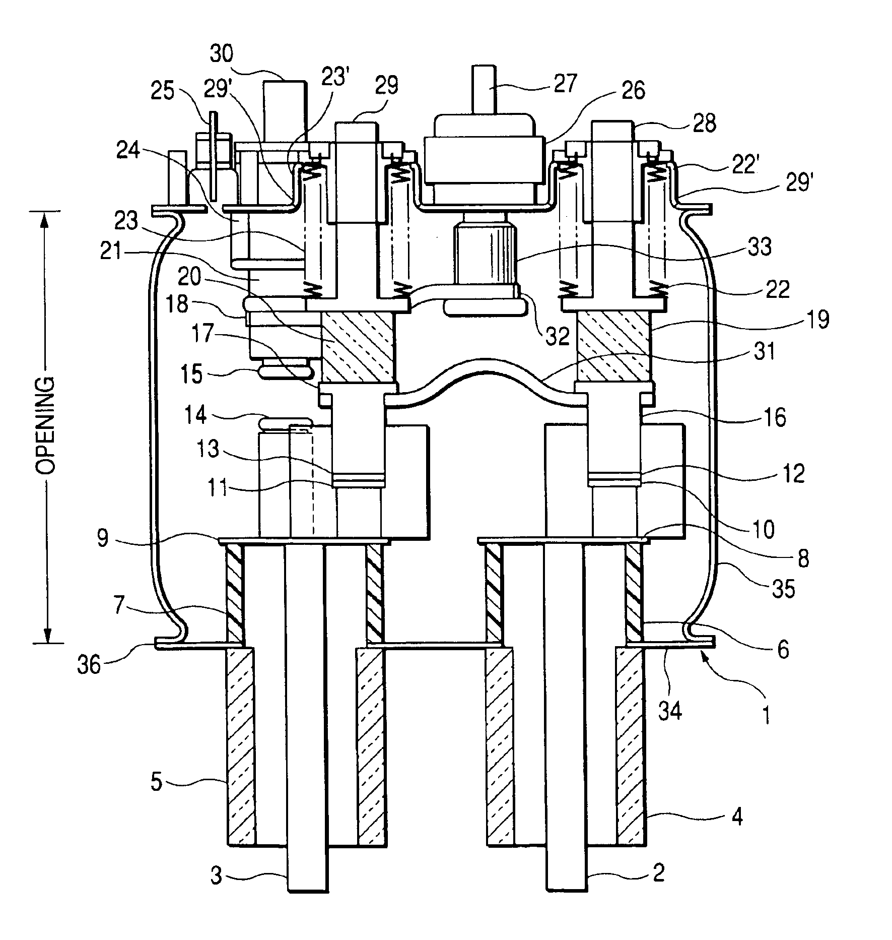
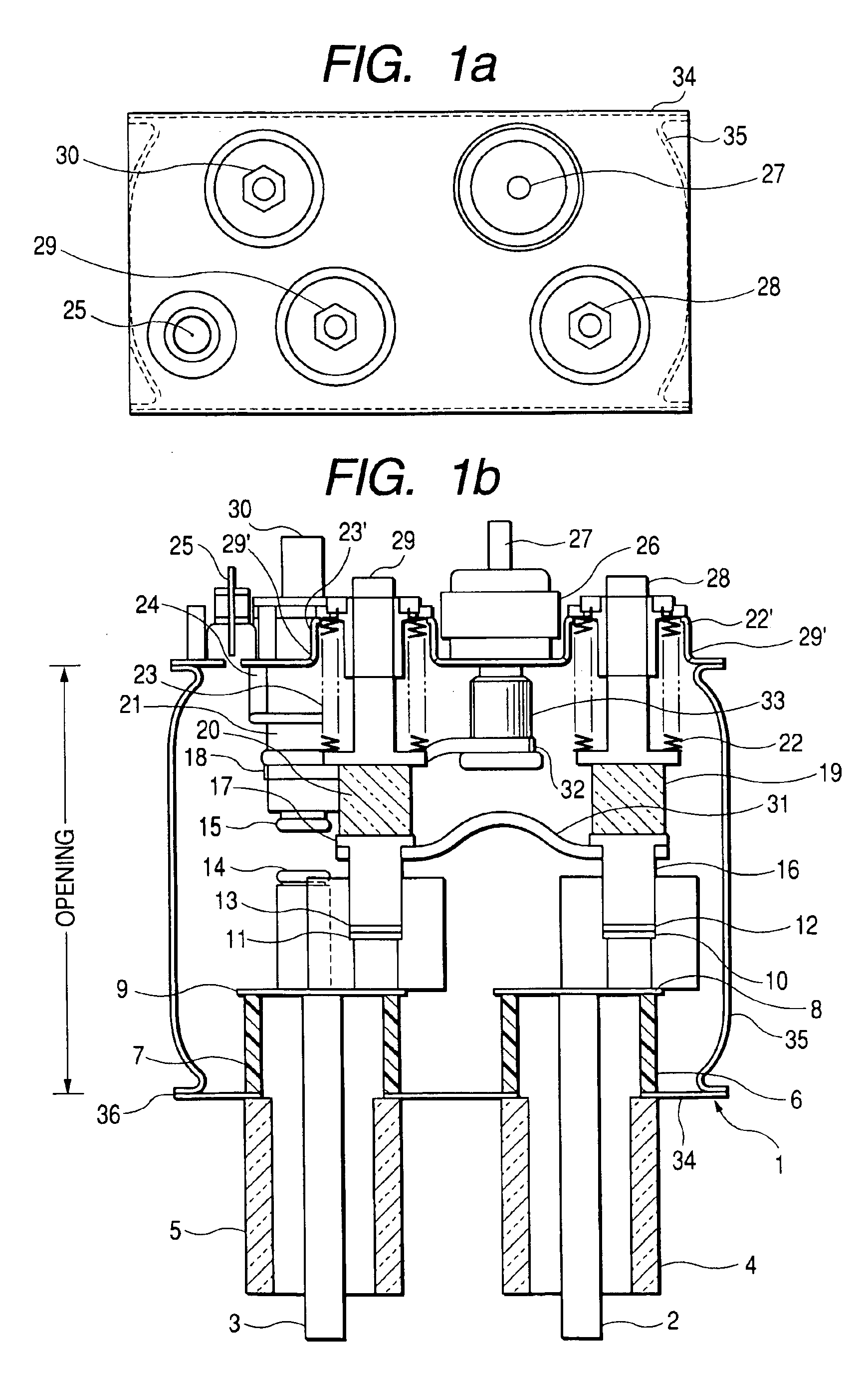
[0037]FIG. 1a and FIG. 1b show a top view and a cross sectional view of the vacuum switchgear according to an embodiment of this invention, respectively. The vacuum container 1, which is electro-conductive and grounded when installed on sites accommodates movable electrodes 12, 13 and the fixed electrodes 10, 11 of two circuit breaker or disconnecting switch and a movable electrode 15 and a fixed electrode 14 of a single ground device portion, and is provided with a vacuum pressure measuring terminal 25 of a vacuum pressure monitoring device mounted on the vacuum container 1. As shown in the top view (FIG. 1a), the two circuit breaker portions or disconnecting switch portions being aligned in a row, and a single ground device portion and the external connecting conductor 27 being aligned in a row are arranged in parallel each other.
[0038]Most part of the vacuum container 1 is formed of conductive material such as SUS316L (JIS standard), which is nonmagnetic stainless steel having hi...
embodiment 2
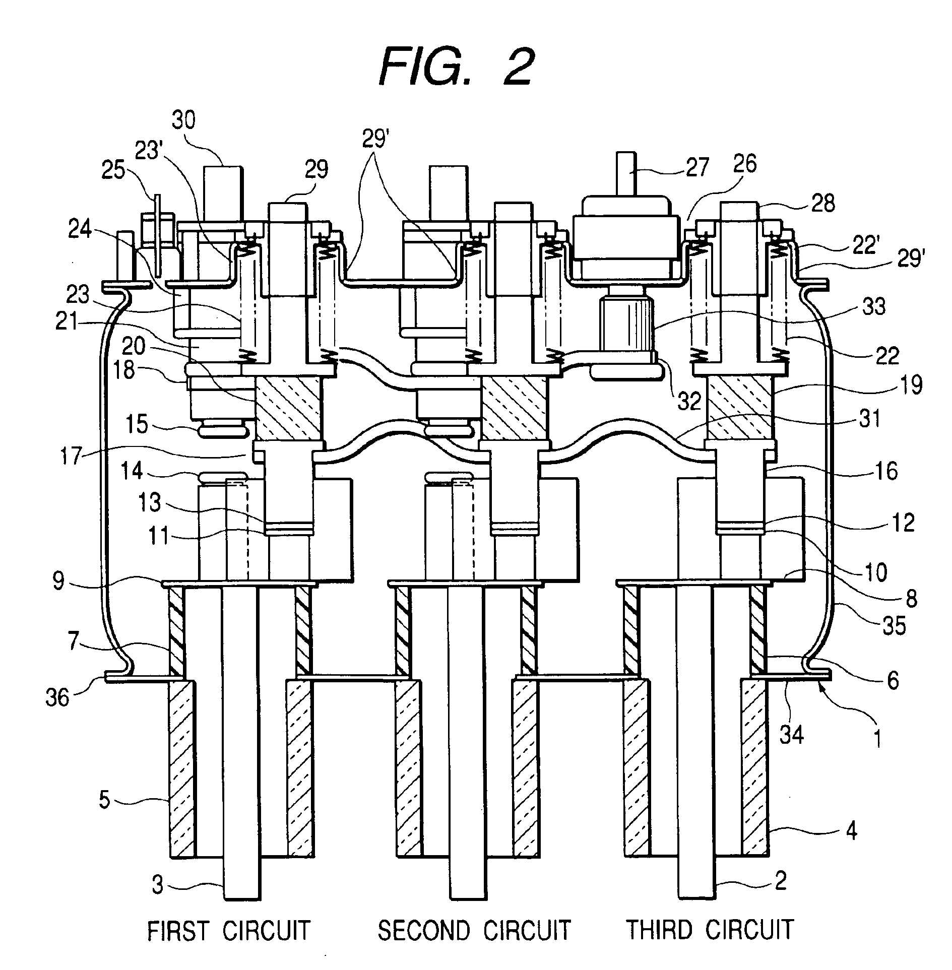
[0053]FIG. 2 is a cross sectional view of the vacuum switchgear according to this invention, and FIG. 3 is a top view of the vacuum switchgear shown in FIG. 2. In the present embodiment, a set of switches for the shutoff portion or for the disconnecting portion and an additional ground switch having electrode contacts 14′, 15′ is further accommodated in the vacuum container, and the circuits are connected by the flexible conductors 31, 32 respectively in addition to Embodiment 1 shown in FIG. 1. The basic structure of the present embodiment is the same as that in Embodiment 1, and the method of manufacturing is also the same. Three sets of switches for the shutoff portion or for the disconnecting portion and two sets of ground switches are accommodated in the vacuum container. The former and the latter are arranged in a staggered pattern. The two sets of ground switches are connected to a single integrated external connecting conductor 27 by the flexible conductor 32.
[0054]The desir...
embodiment 3
[0058]FIG. 4 is a cross sectional view of the vacuum switchgear of this invention and FIG. 5 is a top view thereof. The basic structure of the present embodiment is the the same as that of Embodiment 1, and the method of manufacturing is also the same. In the present embodiment, a switch for the shutoff portion or for the disconnecting portion and the ground switch are further accommodated in the vacuum container, and the respective circuits are connected through the flexible conductors 31, 32 respectively in addition to Embodiment 2 shown in FIG. 1. At least four sets of switches for the shutoff portion or for the disconnecting portion and at least three sets of ground switches are accommodated in the vacuum container. The former and the latter are arranged in a staggered pattern.
[0059]Likewise, in the vacuum container accommodating at least three circuits as in this embodiment, the desired circuits may be grounded by connecting the respective circuits by the flexible conductor 31,...
PUM
 Abstract
Description
Claims
Application Information