Stator for a dynamoelectric machine

Active Publication Date: 2005-04-19
MITSUBISHI ELECTRIC CORP
View PDF11 Cites 9 Cited by
  • Summary
  • Abstract
  • Description
  • Claims
  • Application Information

AI Technical Summary

Benefits of technology

[0011]Therefore, a stator for a dynamoelectric machine is obtained enabling wire breakages in the stator winding and propagation of vibration to a dynamoelectric machine case to be suppressed by correcting

Problems solved by technology

Thus, when an automotive alternator mounted with the stator is mounted to an automotive vehicle, the lead wires vibrate when the stator is subjected to vibrations from the engine, etc., thereby subjecting the stator winding to vibration.
As a result, one disadvantage has been that the vibration to which the stator is subjected is amplified by the

Method used


Image

  • Stator for a dynamoelectric machine
  • Stator for a dynamoelectric machine
  • Stator for a dynamoelectric machine

Examples


embodiment 1

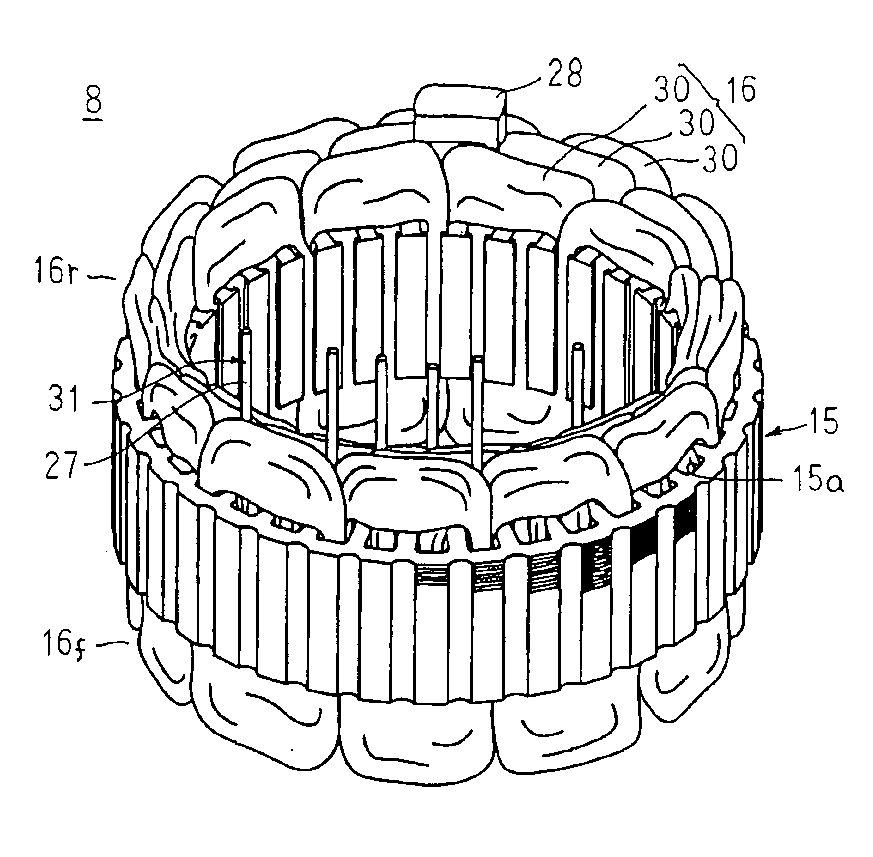
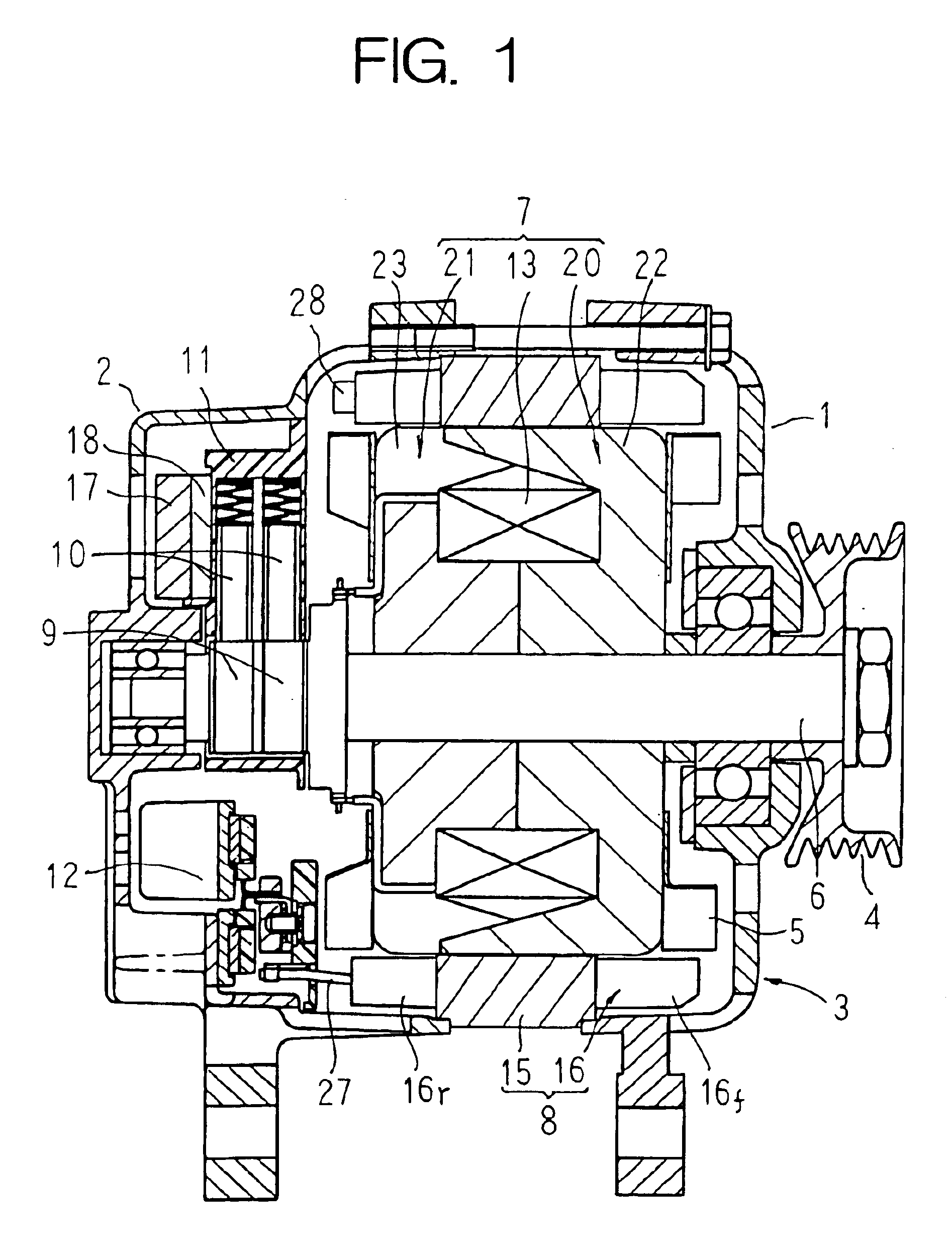
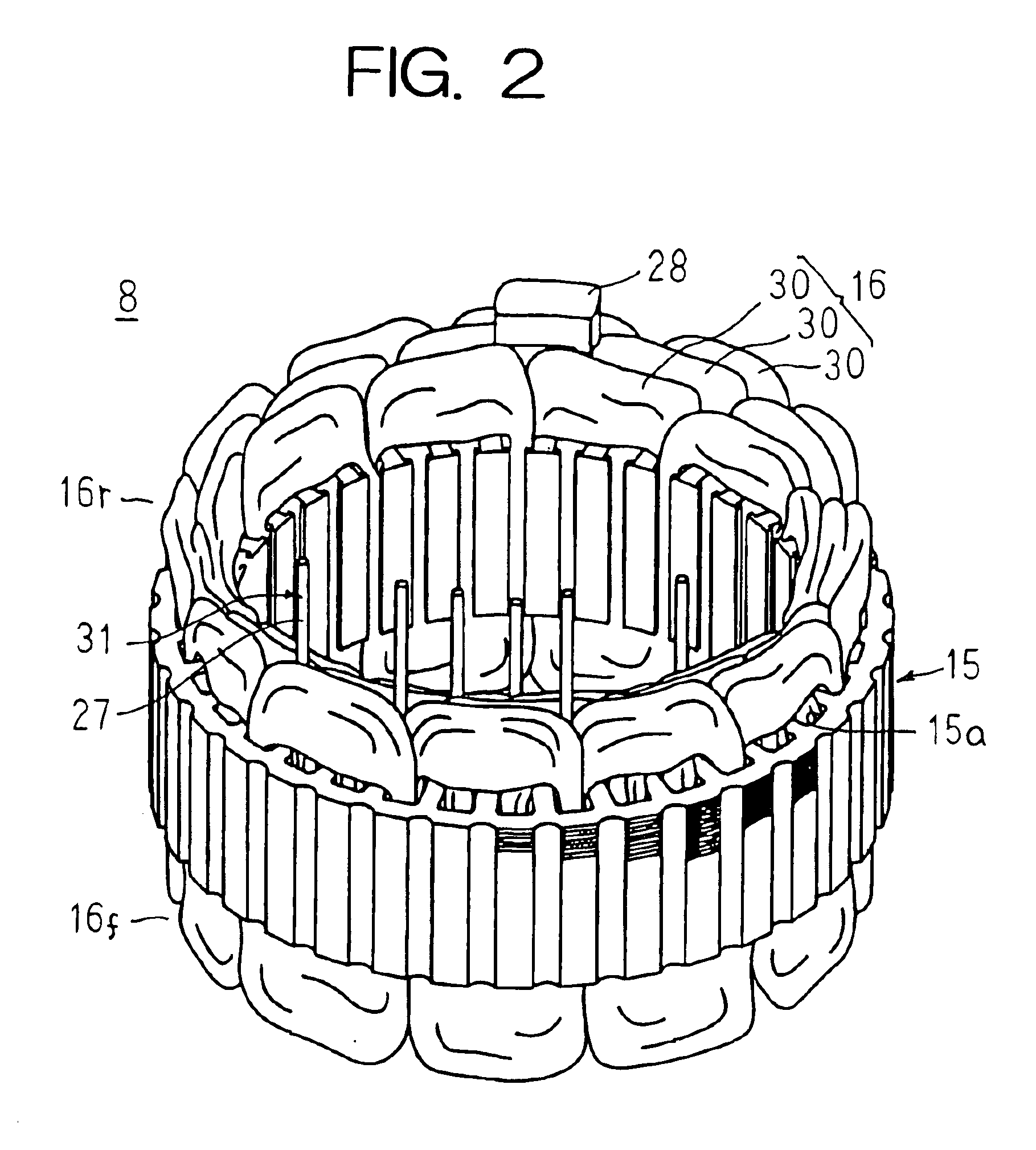
[0029]FIG. 1 is a longitudinal section showing an automotive alternator according to Embodiment 1 of the present invention, FIG. 2 is a perspective of a stator of the automotive alternator according to Embodiment 1 of the present invention viewed from a rear end, FIGS. 3A to 3C are process diagrams explaining a method for manufacturing a stator winding used in the stator of the automotive alternator according to Embodiment 1 of the present invention, and FIG. 4 is a perspective schematically showing a winding phase portion constituting the stator winding used in the stator of the automotive alternator according to Embodiment 1 of the present invention.

[0030]In FIGS. 1 and 2, an automotive alternator is provided with: a case 3 constituted by a front bracket 1 and a rear bracket 2 made of aluminum; a shaft 6 disposed inside the case 3, a pulley 4 secured to a first end portion of the shaft 6; a Lundell-type rotor 7 secured to the shaft 6; fans 5 secured to first and second axial end p...

embodiment 2

[0048]FIG. 5 is a perspective schematically showing a stator of an automotive alternator according to Embodiment 2 of the present invention, and FIG. 6 is a cross section taken along line VI—VI in FIG. 5 viewed from the direction of the arrows.

[0049]In FIGS. 5 and 6, a second mass adjusting portion 29 is mounted to an apex portion of the front-end coil end group16f to adjust an imbalance in mass between the front end and the rear end of the stator core 15 relative to a plane 26 perpendicular to the central axis 25 at an axial center of the central axis 25 (an axial mass imbalance).

[0050]Moreover, Embodiment 2 is constructed in a similar manner to Embodiment 1 above except for the fact that the second mass adjusting portion 29 is provided.

[0051]In this stator 8A, because the height Hf of the front-end coil end group 16f and the height Hr of the rear-end coil end group 16r are equal, the mass at the front end and the rear end of the stator 8A would be balanced relative to the plane 26...

embodiment 3

[0054]FIG. 7 is a perspective schematically showing a stator of an automotive alternator according to Embodiment 3 of the present invention, and FIG. 8 is a cross section taken along line VIII—VIII in FIG. 7 viewed from the direction of the arrows.

[0055]In FIGS. 7 and 8, a second mass adjusting portion 29 is mounted to an apex portion of the front-end coil end group 16f to adjust an imbalance in mass between the front end and the rear end of the stator core 15 relative to a plane 26 perpendicular to the central axis 25 at an axial center of the central axis 25 (an axial mass imbalance).

[0056]In this stator 8B, because the height Hr of the rear-end coil end group 16r is higher than the height Hf of the front-end coil end group 16f, the mass at the rear end of the stator 8B would be greater than the mass at the front end relative to the plane 26 even if there were no lead wires 27 and no first mass adjusting portion 28.

[0057]In Embodiment 3, a second mass adjusting portion 29 is mount...


PUM


Abstract

A stator for a dynamoelectric machine includes an annular stator core in which a large number of slots extending in an axial direction are disposed in a circumferential direction so as to open radially inward; a stator winding having a plurality of winding phase portions installed in the stator core, lead wires of the plurality of winding phase portions being led axially outward within a predetermined circumferential range from an axial end of a first coil end group formed at a first axial end of the stator core; and a first mass adjusting portion disposed at a first end of the stator core, the first mass adjusting portion adjusting a circumferential mass imbalance relative to a central axis of the stator core resulting from a circumferential bias in positions from which the lead wires are led out.

Description

BACKGROUND OF THE INVENTION[0001]1. Field of the Invention[0002]The present invention relates to a stator for a dynamoelectric machine such as an automotive alternator, etc., and particularly relates to a stator construction for correcting circumferential mass imbalances caused by lead wires of a stator winding.[0003]2. Description of the Related Art[0004]A conventional stator for an automotive alternator is constituted by: an annular stator core in which slots extending in an axial direction are disposed at a predetermined pitch in a circumferential direction so as to open radially inward; and a stator winding installed in the stator core. The stator winding is constituted by three winding phase portions, the positions at which lead wires of each of the winding phase portions are led out from a rear-end coil end group being distributed within a circumferential range of approximately 120 degrees centered around a central axis of the stator core. Each of the lead wires is led axially...

Claims


Application Information

Patent Timeline
IPC IPC(8): H02K7/00H02K7/04H02K3/50H02K15/02
CPCH02K7/04H02K3/50
Inventor HIGASHINO, KYOKOKASHIHARA, TOSHIAKI
Owner MITSUBISHI ELECTRIC CORP
Why Eureka
Try Eureka