Video signal processing apparatus

a video signal and processing apparatus technology, applied in the field of video signal processing apparatuses, can solve problems such as flicker, and achieve the effect of superior video signal processing apparatus

Inactive Publication Date: 2005-04-19
PANASONIC CORP
View PDF23 Cites 30 Cited by
  • Summary
  • Abstract
  • Description
  • Claims
  • Application Information

AI Technical Summary

Benefits of technology

[0010]The aim of the present invention is to prov

Problems solved by technology

When image is taken by a video camera under illuminati

Method used


Image

  • Video signal processing apparatus
  • Video signal processing apparatus
  • Video signal processing apparatus

Examples


Embodiment Construction

[0022]Hereinbelow will be described an embodiment of this invention.

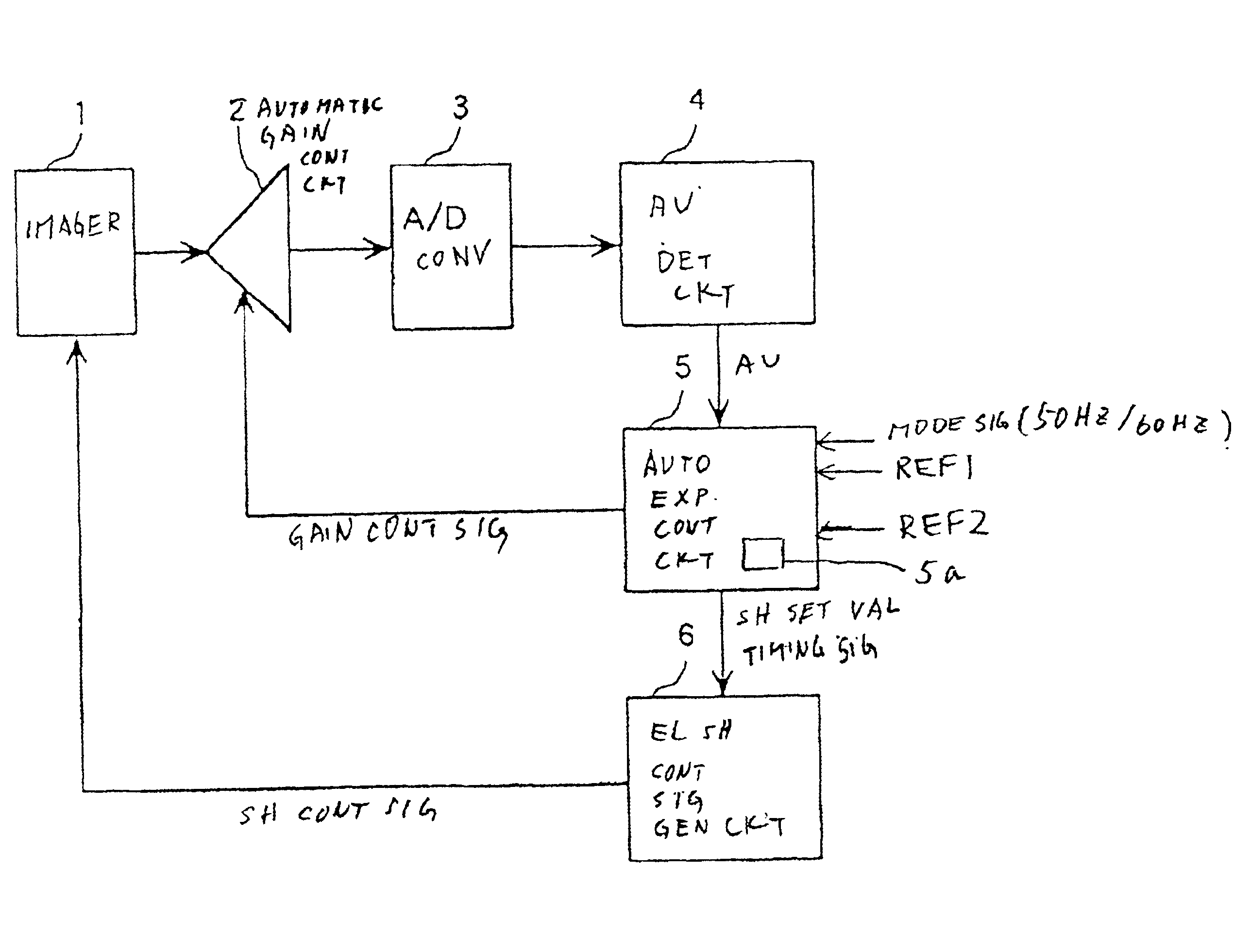
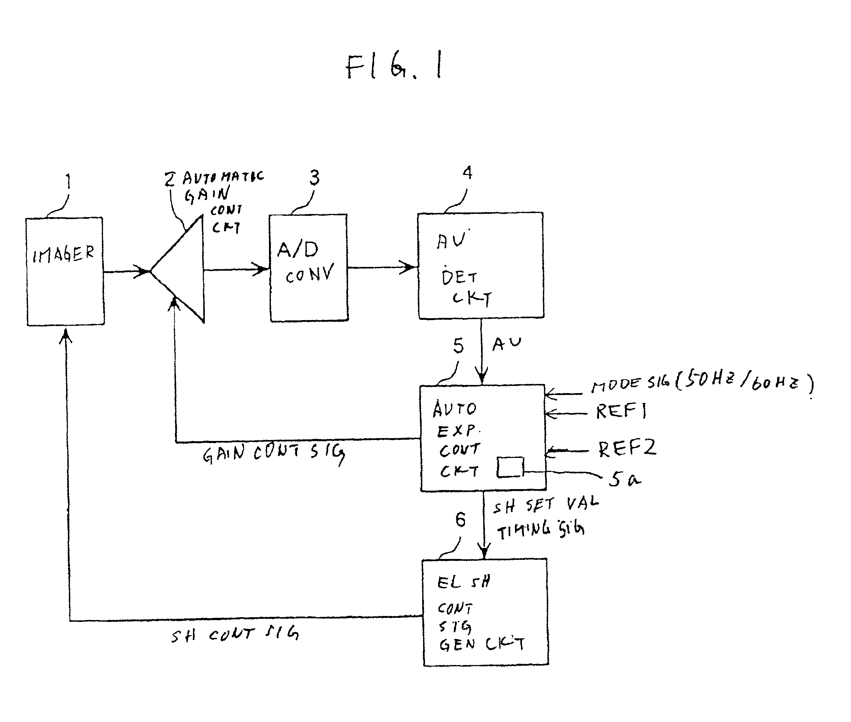
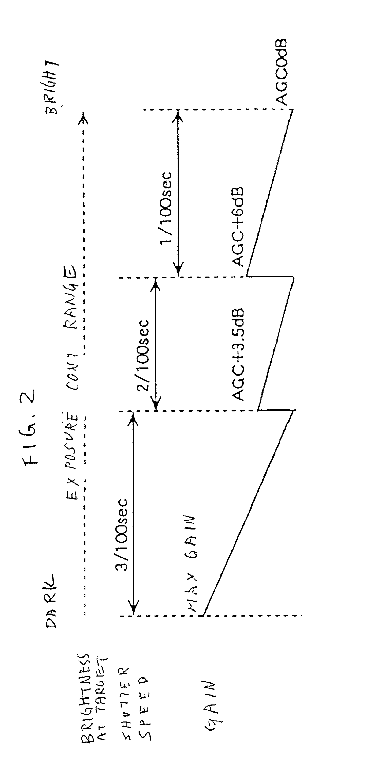
[0023]FIG. 1 shows a video signal processing apparatus of this embodiment, wherein an imager is also shown. FIG. 2 shows variations of the shutter speed of the imager and a gain of the video signal from the imager.

[0024]The video signal processing apparatus of this embodiment includes: an automatic gain controlling circuit 2 for controlling a gain of a video signal from an imager 1 having an electronic shutter function in accordance with a gain control signal; an a / d converter 3 for converting a video signal from the automatic gain controlling circuit 2 into a digital video signal, an average detecting circuit 4 for detecting an average level of a luminance signal of the digital video signal (luminance average level of the digital video signal); an automatic exposure controlling circuit 5 responsive to a mode signal indicative of the cycle per second of the ac line at the area for generating the gain control signal ...


PUM


Abstract

An automatic gain controlling circuit controls a gain of a video signal from an imager having an electronic shutter function according to a gain control signal. An average detecting circuit detects an average level of a luminance signal of the video signal. An automatic exposure controlling circuit generates the gain control signal according to the luminance average level in response to a mode signal indicative of the cycles per second of the ac line and generates a timing signal corresponding to the ac line and a shutter speed control signal together with electronic shutter control signal generation circuit at a unit of the voltage variation cycle of the ac line according to the luminance average level such that a shutter interval of the imager is changed stepwise and each of the shutter intervals is an integer times the voltage variation cycle of the ac line. The automatic exposure controlling range is expanded by changing the shutter speed stepwise from {fraction (1/100)} sec, {fraction (2/100)} sec {fraction (3/100)} sec at 50-Hz-ac area, for example, to provide coarse exposure controlling and fine automatic gain controlling is provided every shutter interval to suppress flicker.

Description

BACKGROUND OF THE INVENTION[0001]1. Field of the Invention[0002]This invention relates to a video signal processing apparatus. More specifically, this invention relates to a video signal processing apparatus for processing a video signal to reduce flicker.[0003]2. Description of the Prior Art[0004]A video signal processing apparatus for processing a video signal in which flicker due to illumination is suppressed with an automatic gain controlling circuit is known.[0005]When image is taken by a video camera under illumination by fluorescent lamps, there is a problem of flicker. A luminance level of the fluorescent lamp periodically changes with a voltage of the ac line. FIGS. 3A and 3B are illustrations of prior art showing voltage change and luminance change of fluorescent lamps. If the cycle of the voltage of ac line is 50 Hz as shown in FIG. 3A, the luminance of a fluorescent lamp changes at 100 Hz as shown in FIG. 3B. If the cycle of the voltage of an ac line is 60 Hz, the lumina...

Claims


Application Information

Patent Timeline
IPC IPC(8): H04N5/235H04N5/243H04N5/238H04N5/335H04N5/351H04N5/21H04N5/353H04N5/355H04N5/357H04N5/369H04N5/372H04N5/374H04N5/378
CPCH04N5/235H04N5/243H04N5/2357H04N23/70H04N23/745H04N23/76
Inventor ODA, KAZUOKARIYA, MASAKI
Owner PANASONIC CORP
Why Eureka
Try Eureka