Chip-type capacitor, method of manufacturing the same and molding die

a technology of chip-type capacitors and molding dies, which is applied in the manufacture of capacitors, fixed capacitor details, liquid electrolytic capacitors, etc., can solve the problems of increased production cost and production time, lead-time, electric characteristics and reliability of capacitors will be deteriorated, and production cost increas

Active Publication Date: 2005-04-19
TOKIN CORP
View PDF4 Cites 32 Cited by
  • Summary
  • Abstract
  • Description
  • Claims
  • Application Information

AI Technical Summary

Benefits of technology

[0013]Accordingly, it is an object of the present invention to provide a chip-type capacitor which is capable of forming a fillet esse...

Problems solved by technology

The application of the plating process results in an increase in production cost and production time (lead-time).
Furthermore, there arises a problem that, if a liquid leaks into the inside of the encapsulation resin during a series of plating processes such as degreasing, plating, cleaning and rust-proofing, the electric characteristics and the reliability of the capacitor will be deteriorated.
However, in the chip-type capacitors described in References 1 and 2, a lead frame (str...

Method used


Image

  • Chip-type capacitor, method of manufacturing the same and molding die
  • Chip-type capacitor, method of manufacturing the same and molding die
  • Chip-type capacitor, method of manufacturing the same and molding die

Examples


Embodiment Construction

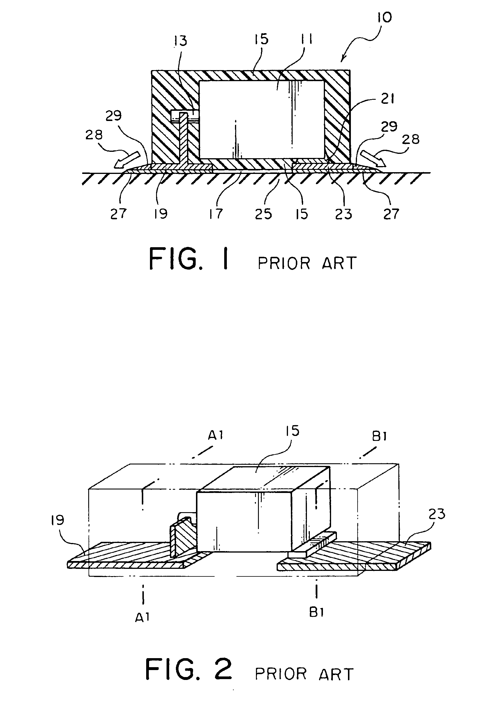
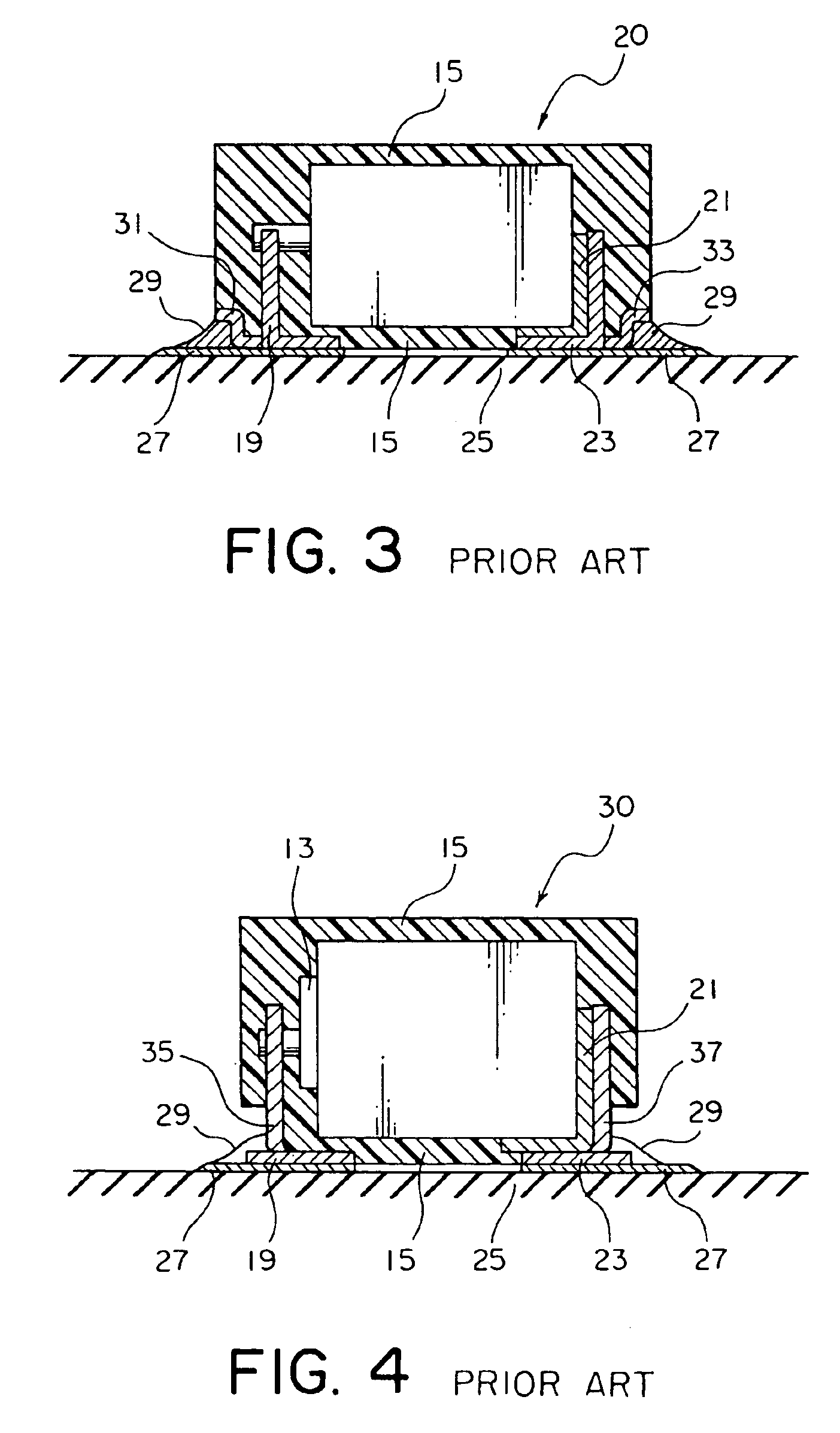
[0029]Prior to description of embodiments according to the present invention, several known chip-type capacitors will be described with reference to FIGS. 1 through 4.

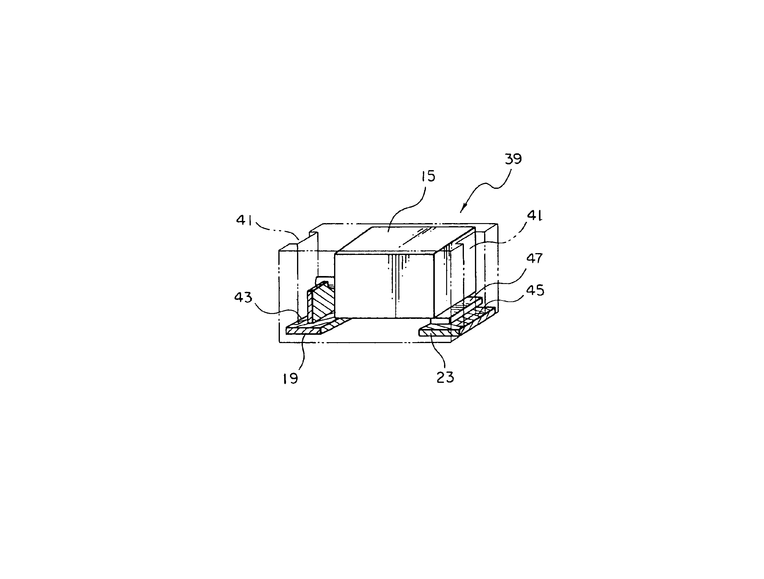
[0030]Referring to FIGS. 1 and 2, an existing chip-type capacitor 10 includes a capacitor element 11, an encapsulation resin 15, an anode terminal 19, and a cathode terminal 23. The capacitor element 11 is produced by preparing powder of a valve action metal, burying an anode lead wire 13 in the powder with its one end led out from the powder, molding and sintering the powder to form a porous anode body, forming a dielectric oxide film (not shown) on the anode body by a known technique, and successively forming, on a surface of the dielectric oxide film, an electrolyte layer (not shown) and a cathode layer (not shown).

[0031]The anode terminal 19 has a base portion whose bottom surface is exposed on a mounting surface 17 of the encapsulation resin 15 and a standing-up portion perpendicular to the base portion. The anode...


PUM

PropertyMeasurementUnit
Lengthaaaaaaaaaa
Thicknessaaaaaaaaaa
Electrical conductoraaaaaaaaaa

Abstract

A chip-type capacitor includes a capacitor element, an encapsulation resin covering an entirety of the capacitor element, an anode terminal having a base portion whose bottom surface is exposed on a mounting surface of the encapsulation resin and a standing-up portion perpendicular to the base portion and having one end connected to the base portion and the other end welded to an anode lead wire led out from the capacitor element, and a cathode terminal fixed through a conductive adhesive to the capacitor element so as to expose a bottom surface on the mounting surface of the encapsulation resin. A depressed portion is formed on each of opposite side surfaces of the encapsulation resin, thereby partially exposing a top surface of each of the anode and the cathode terminals opposite to the bottom surface to form a terminal exposed portion exposed out of the encapsulation resin.

Description

[0001]The present application claims priority to prior Japanese application JP 2003-37045, the disclosure of which is incorporated herein by reference.BACKGROUND OF THE INVENTION[0002]The present invention relates to a chip-type capacitor having a resin-encapsulated structure, a method of manufacturing the same and a molding die.[0003]An existing chip-type capacitor of the type includes a capacitor element, an anode terminal, a cathode terminal, and an encapsulation resin covering these components.[0004]A capacitor element is produced by preparing powder of a valve action metal, burying an anode lead wire in the powder with its one end led out from the powder, molding and sintering the powder to form a porous anode body, forming a dielectric oxide film on the anode body by a known technique, and successively forming, on a surface of the dielectric oxide film, an electrolyte layer and a cathode layer. Furthermore, the anode terminal has a base portion having a bottom surface exposed ...

Claims


Application Information

Patent Timeline
IPC IPC(8): H01G9/00H01G9/004H01G9/008H01G9/08H01G4/228H01G13/00H01G2/06H01G9/012H01G9/042H01G9/10
CPCH01G2/065H01G9/012H01G9/10H01G9/042Y10T29/417H01G9/004
Inventor TSUTSUI, MAKOTONAGASAWA, TOSHIHISA
Owner TOKIN CORP
Why Eureka
Try Eureka