Method and apparatus for input rate regulation associated with a packet processing pipeline

a packet processing and input rate regulation technology, applied in the field of network general, can solve the problems of relatively inefficient consumption of network resources, waste of bandwidth, packet networks generally characterized as having poor latency but good efficiency

Inactive Publication Date: 2005-04-19
NOKIA SOLUTIONS & NETWORKS OY
View PDF35 Cites 86 Cited by
  • Summary
  • Abstract
  • Description
  • Claims
  • Application Information

AI Technical Summary

Problems solved by technology

Low latency is deemed a requirement for networks carrying voice traffic since two people engaged in conversation begin have difficulty communicating effectively if there is more than 10-100 milliseconds of delay in the transport of their correspondence.
A problem with circuit networks, however, is their relatively inefficient consumption of network resources (in the form of wasted bandwidth).
Packet networks have been generally characterized as having poor latency but good efficiency.
Traditionally, the transportation of traffic over a packet network resulted in noticeable delay (i.e., high latency).
However, with a packet network, bandwidth tends to be conserved rather than wasted.
With the poorer efficiency of circuit switched networks, the surge in non real time traffic and the potential of packet networks to carry real time traffic, WAN / RN network managers have begun to think about a packet based approach in the WAN and RN.
Again, if the user receives traffic at too high a rate, the service provider is not necessarily obligated to deliver it; or at least deliver all of it.
For example, voice traffic typically requires small delay through the network while data traffic may tolerate higher delays.

Method used


Image

  • Method and apparatus for input rate regulation associated with a packet processing pipeline
  • Method and apparatus for input rate regulation associated with a packet processing pipeline
  • Method and apparatus for input rate regulation associated with a packet processing pipeline

Examples


embodiment 495

[0085]The embodiment 495 of FIG. 4 may be used for an Internet Protocol version 4 (IPv4) application or other applications as well. As shown in FIG. 4, the header information 417 may at least partially include: 1) Source Port Address (SP); 2) Destination Port Address (DP); 3) Source Address (SA); 4) Destination Address (DA); 5) Next Hop Route Address (NHA); 6) Protocol ID (PID); 7) Type of Service (TOS); and 8) Length (L). The relevance of the header based information 417 is apparent to those who practice in the art. The calculated control information 402, in the embodiment of FIG. 4, includes a packet identifier 408, a length indicator 404 (also referred to as packet size), a time stamp insert flag 406 and a record route flag 407.

[0086]The packet identifier 408 indicates where a packet is located in the packet buffer memory. As discussed previously, the pipeline eventually stores packet identifier 408 into an output packet organizer location. In various embodiments, packets may be ...

embodiment 540

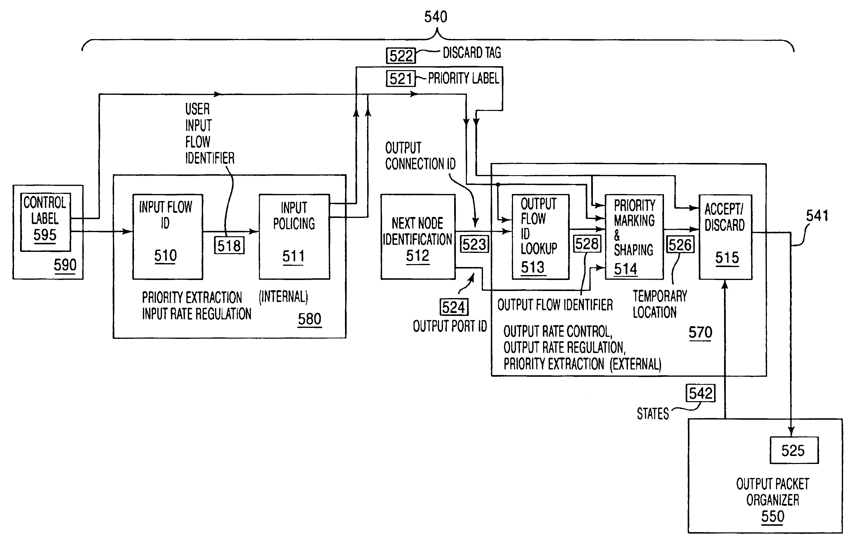
[0092]FIG. 5d shows an embodiment 540 of a packet processing pipeline, such as the packet processing pipeline 340 of FIG. 3. A packet processing pipeline 540 is a sequence of stages where various stages are tailored to implement networking related tasks on a packet. Such stages may be referred to as networking stages. Each networking stage is devoted to implementing a portion of the overall processing that a packet can be subjected to in being converted from an input packet to an output packet.

[0093]The order or sequence of the networking stages within a pipeline (which may now be referred to as stages for simplicity) correspond to the order or sequence in which operations are performed on a packet. For example, the packet processing pipeline embodiment 540 of FIG. 5d has six stages: 1) an Input Flow ID stage 510; 2) an Input Policing stage 511; 3) a Next Node Identification stage 512; 4) an Output Flow ID stage 513; 5) a Priority Marking and Shaping stage 514; and 6) an Accept Disc...

embodiment 911

[0157]Recall in the packet processing embodiment of FIGS. 7a and 7b, the user input flow identifier 718b is implemented as a memory pointer that is used by the input policing stage 711a to look up a user input flow. An embodiment 911 of the input policing stage 711a of FIG. 7a is shown in FIG. 9. The look up based upon the user input flow identifier 918b occurs in flow table 720, 920. Flow table 920 shows a left hand column 902, implemented as memory address spaces, having a list 918l-q of the various user input flow identifiers 818l-q of FIG. 8) supported by the system. The right hand column 903 shows a listing of user input flows 919l-q that are identified by each of the user input flow identifiers 918l-q.

[0158]User input flows, as discussed, may be at least partially defined by a combination of input rate regulation and priority parameters. Such terms are reflected in the user input flows 919l-q of FIG. 9. In the flow table embodiment 920 of FIG. 9, the priority parameter is repr...


PUM


Abstract

A method is described that involves presenting packet header information from a packet and packet size information for the packet to a pipeline that comprises multiple stages. One of the stages identifies, with the packet header information, where input flow information for the packet is located. The input flow information is then fetched. The input flow information identifies where input capacity information for the packet is located and the input capacity information is then fetched. Another of the stages compares an input capacity for the packet with the packet's size and indicates whether the packet is conforming or non-conforming based upon the comparison. The input capacity is calculated from the input capacity information.

Description

FIELD OF INVENTION[0001]The field of invention relates to networking generally. More specifically, the field of invention relates to a pipeline for processing networking packets.BACKGROUND OF THE INVENTIONPacket Networks[0002]Two forms of networking technology, referred to as “circuit” and “packet” are in widespread use. However, the two have generally been applied to different applications. Circuit networks, usually associated with large telecommunications companies, have traditionally supported mostly voice traffic (e.g., a telephone call) while packet networks have traditionally supported computer traffic (commonly referred to as data traffic or the like).[0003]Circuit networks are generally characterized as having minimal latency, meaning: traffic emanating from a source appears almost instantaneously at its destination. Low latency is deemed a requirement for networks carrying voice traffic since two people engaged in conversation begin have difficulty communicating effectively...

Claims


Application Information

Patent Timeline
Patent Type & Authority Patents(United States)
IPC IPC(8): H04L12/24H04L12/56
CPCH04L47/10H04L47/20H04L47/41H04L47/2441H04L47/31H04L47/2408H04L41/5003
Inventor KEJRIWAL, PRABHASHO, CHI FAI
Owner NOKIA SOLUTIONS & NETWORKS OY
Why Eureka
Try Eureka