

Method and device for displaying or searching for object in image and computer-readable storage medium
- Summary
- Abstract
- Description
- Claims
- Application Information
AI Technical Summary
Benefits of technology
Problems solved by technology
Method used
Image

Examples
first embodiment
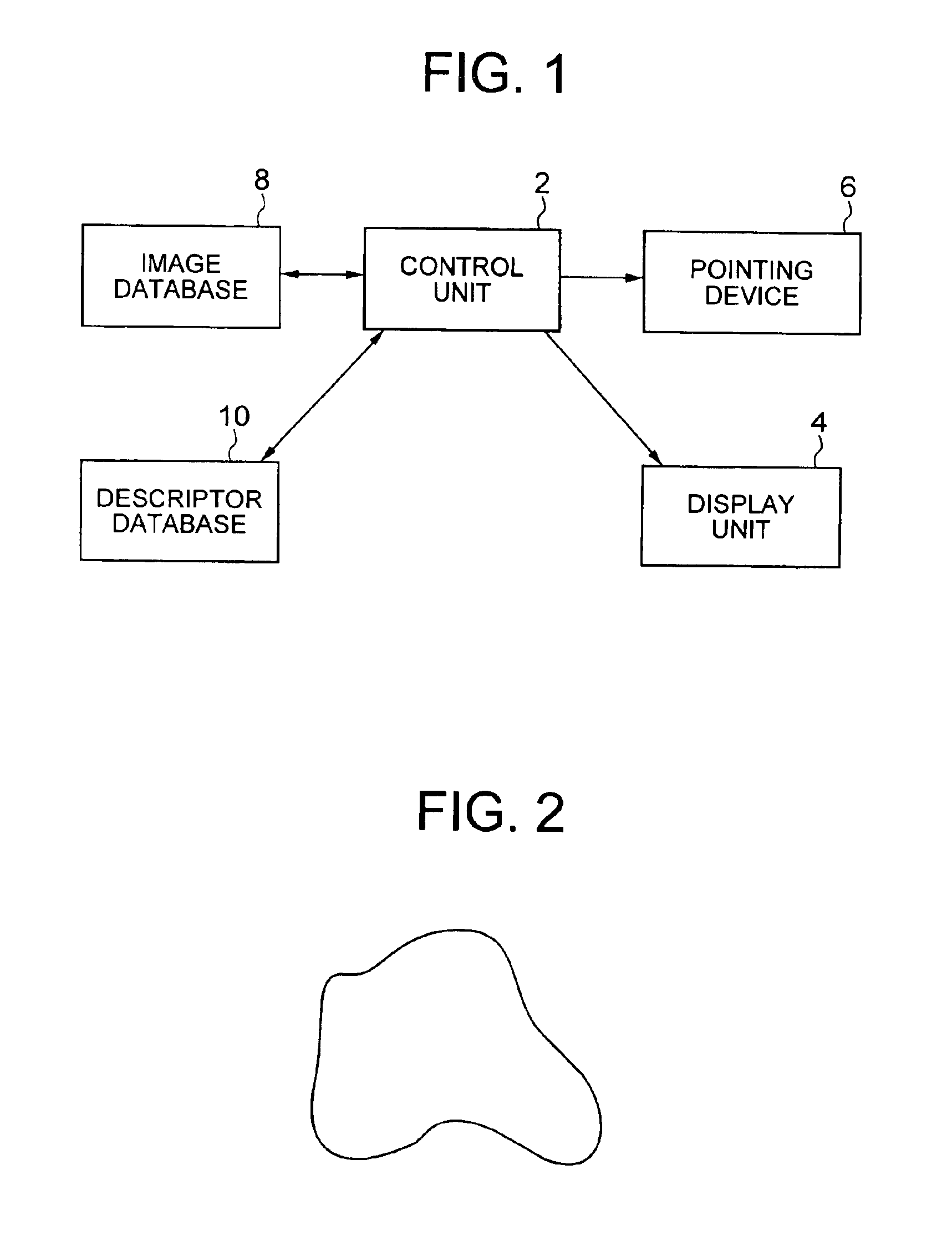
[0036]FIG. 1 shows a computerised video database system according to an embodiment of the invention. The system includes a control unit 2 in the form of a computer, a display unit 4 in the form of a monitor, a pointing device 6 in the form of a mouse, an image database 8 including stored still and video images and a descriptor database 10 storing descriptors of objects or parts of objects appearing in images stored in the image database 8.
[0037]A descriptor for the shape of each object of interest appearing in an image in the image database is derived by the control unit 2 and stored in the descriptor database 10. The control unit 2 derives the descriptors operating under the control of a suitable program implementing a method as described below.
[0038]Firstly, for a given object outline, a CSS representation of the outline is derived. This is done using the known method as described in one of the papers mentioned above.
[0039]More specifically, the outline is expressed by a represent...
second embodiment
[0054]An alternative method of representing the object outline according to a second embodiment will now be described.
[0055]A CSS representation of the outline is derived as described above. However, the ordering of the peak co-ordinates is different from the ordering in Embodiment 1 described above. More specifically, firstly the highest peak is selected. Suppose peak k is the most prominent one. Then (xk,yk) becomes the first peak in the ordered set of peaks. The subsequent peaks are ordered so that for peak co-ordinates of original index i, then T(i)=j, and xj<=x(j+1). Also, all values xi are shifted downwards by an amount xk equal to the original x co-ordinate of original peak k.
[0056]In other words, in the ordering method according to embodiment 2, the highest peak is selected and placed first, and then the remaining peaks follow in the original sequence starting from the highest peak.
[0057]Table 3 below shows the peak values of Table 1 ordered according to the second embodimen...
third embodiment
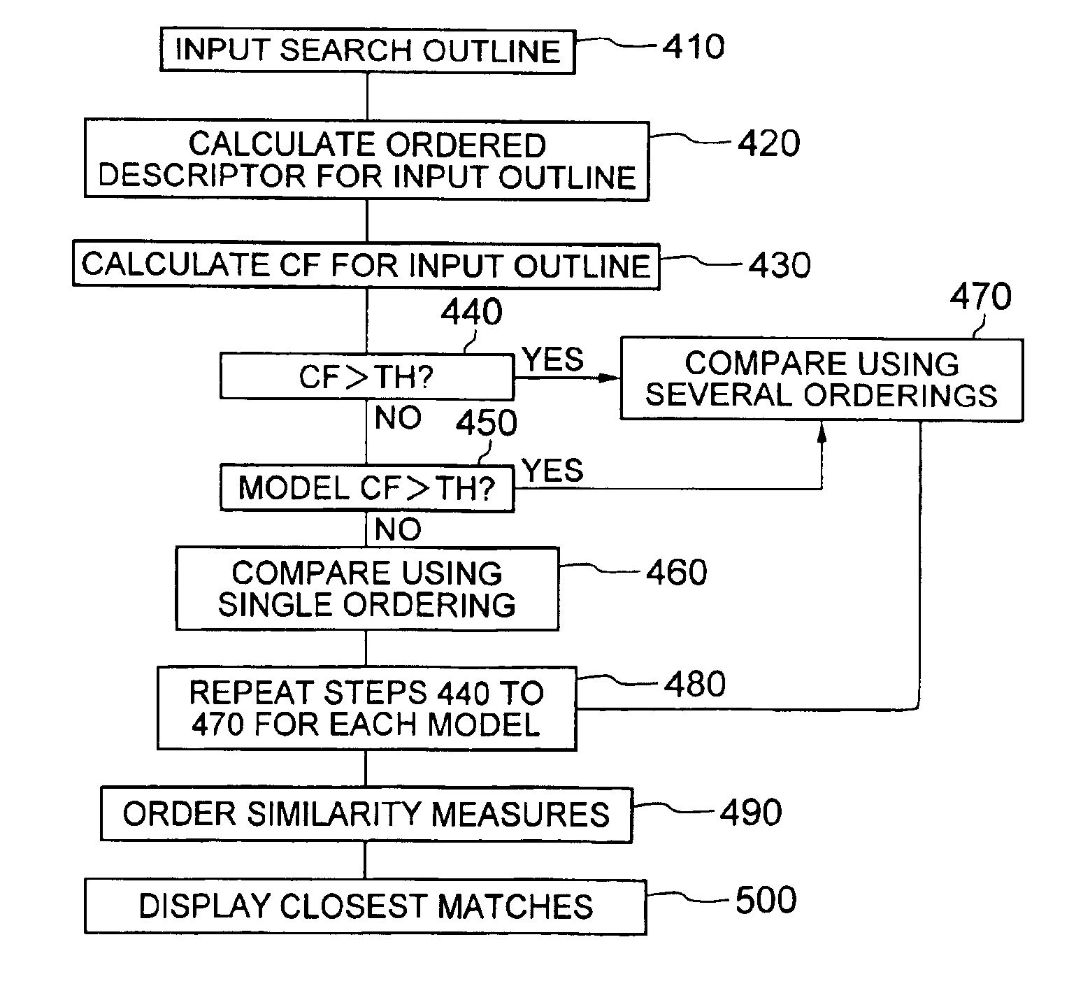
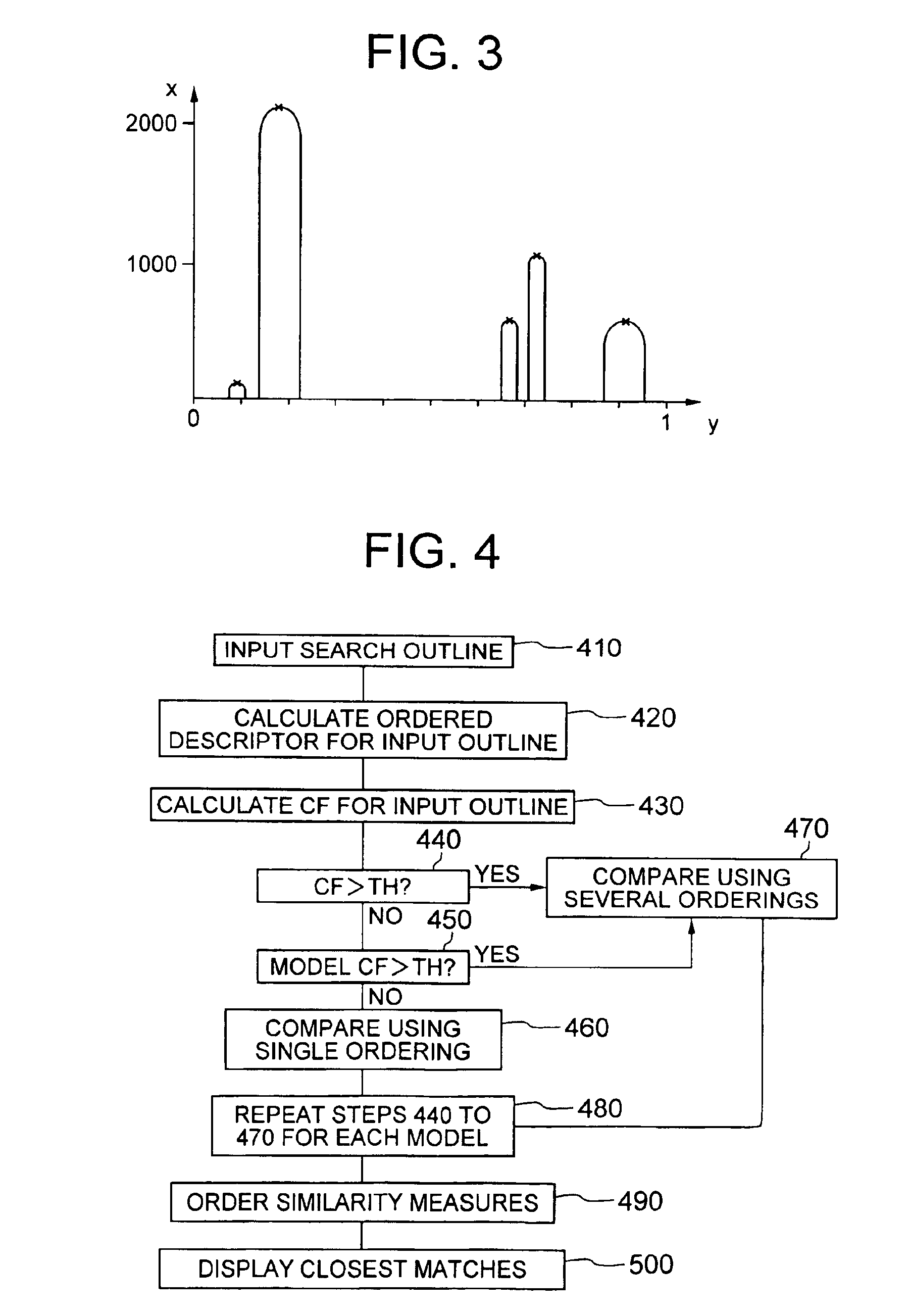
[0063]A method of searching for an object in an image in accordance with an embodiment of the invention will now be described with reference to FIG. 4 which is a block diagram of the searching method.
[0064]Here, the descriptor database 10 of the system of FIG. 1 stores descriptors derived according to the first ordering method described above together with associated CF values.
[0065]The user initiates a search by drawing an object outline on the display using the pointing device (step 410). The control unit 2 then derives a CSS representation of the input outline and orders the peak co-ordinates in accordance with the same ordering function used for the images in the database to arrive at a descriptor for the input outline (step 420). The control unit 2 then also calculates a CF value for the input outline by calculating the ratio of the second highest peak value to the highest peak value and quantizing the result (step 430).
[0066]The control unit 2 then compares the CF value for th...
PUM
 Abstract
Description
Claims
Application Information