
Microprocessor runaway monitoring control circuit

Inactive Publication Date: 2005-04-19
MITSUBISHI ELECTRIC CORP
View PDF15 Cites 32 Cited by
  • Summary
  • Abstract
  • Description
  • Claims
  • Application Information

AI Technical Summary

Benefits of technology

[0010]It is therefore a first object of the present invention to resolve the above-mentioned issues and provide a microprocessor runaway monitoring control circuit with which self-diagnosis of a watchdog timer can be carried out safely and cheaply even during operation of the microprocessor.

Problems solved by technology

Although if a microprocessor is normal a runaway monitoring circuit monitoring it will never operate, if the microprocessor does ever become abnormal and the runaway monitoring circuit fails to operate then, there may be serious danger.
However, there are certain problems associated with the related art described above, and in circuits such as that of Related Art 1, where a watchdog timer for runaway monitoring is just connected to a microprocessor, there are the following kinds of safety issue.
Among these, the problematic aspects are the danger (loss of runaway monitoring function) associated with passive failure of the watchdog timer, and unintentional resetting of the microprocessor caused by active failure.
With respect to this, even with the runaway monitoring control circuit of Related Art 2, there are the shortcomings that if there is an abnormality in a switching circuit which switches the output signal for resetting the microprocessor, there is a danger that it will become impossible for the microprocessor to be reset, and that if the microprocessor runs away while diagnosing the watchdog timer, again the microprocessor will not be reset.

Method used


Image

  • Microprocessor runaway monitoring control circuit
  • Microprocessor runaway monitoring control circuit
  • Microprocessor runaway monitoring control circuit

Examples


Embodiment Construction

[0090][First Preferred Embodiment]

[0091](1) Detailed Explanation of Construction of First Preferred Embodiment

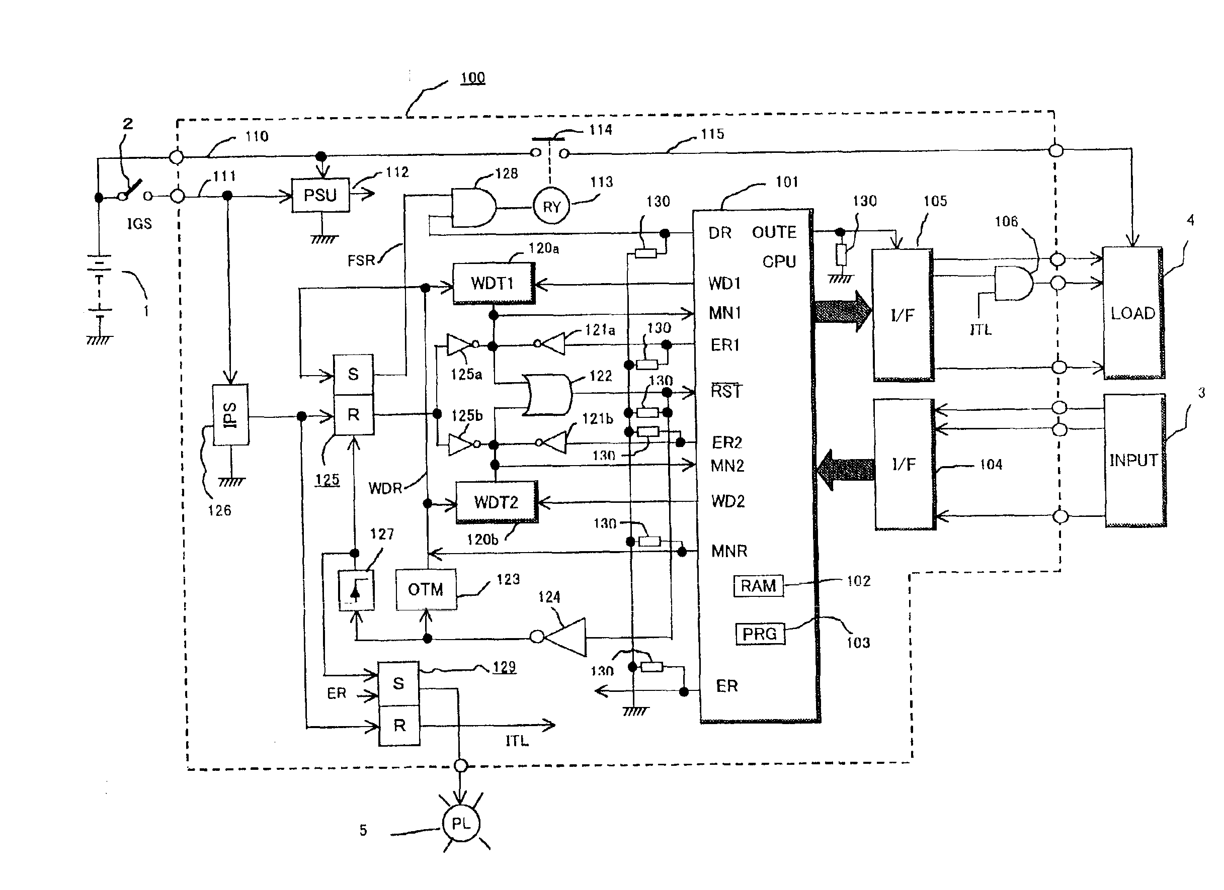
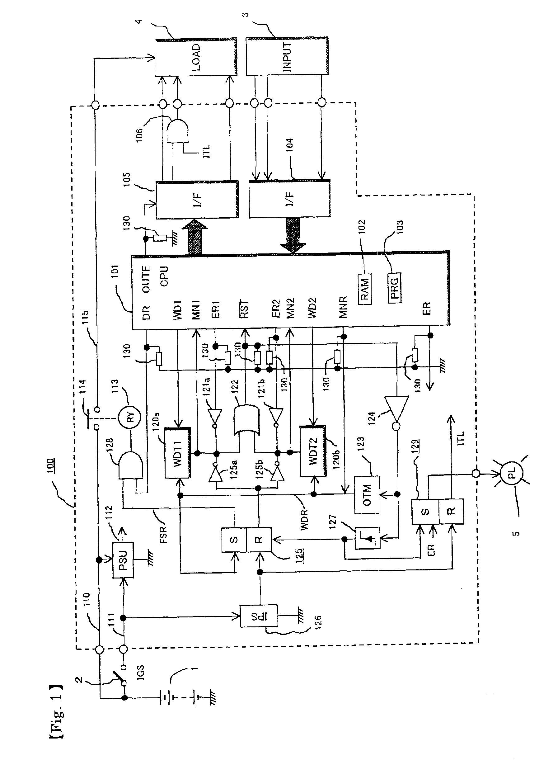
[0092]A block diagram of a first preferred embodiment of a microprocessor runaway monitoring control circuit according to the invention is shown in FIG. 1.

[0093]In FIG. 1, the reference number 100 denotes an electronic apparatus such as an engine control unit for use in an automotive vehicle. A power supply 1 such as for example a vehicle battery is directly connected to this electronic apparatus 100 via a power supply switch 2.

[0094]The reference number 3 denotes a group of input sensors which provide control inputs to the electronic apparatus 100; 4 a group of electrical loads supplied with control outputs by the electronic apparatus 100; and 5 a warning / display device controlled by the electronic apparatus 100. The internal construction of the electronic apparatus 100 will now be described.

[0095]The reference number 101 denotes a microprocessor having a RAM memory 102 for...


PUM


Abstract

A microprocessor runaway monitoring control circuit with which self-diagnosis of a watchdog timer WDT can be carried out safely and cheaply even during operation of the microprocessor (CPU). A microprocessor 101 supplies first and second watchdog clearing signals WD1 and WD2 to first and second watchdog timers WDT1 and WDT2, and when the both of the watchdog clearing signals WD1 and WD2 stop, the microprocessor 101 is reset by way of a logical connector circuit 122. The microprocessor 101 has failure diagnosing means 103 which intentionally stops the first watchdog clearing signal WD1 and diagnoses the response of the first watchdog timer WDT1 on the basis of a monitor signal MN1 and stops the second watchdog clearing signal WD2 and diagnoses the response of the second watchdog timer WDT2 on the basis of a monitor signal MN2, whereby diagnosis of the watchdog timers WDT1, WDT2 is carried out without the microprocessor 101 being stopped.

Description

BACKGROUND OF THE INVENTION[0001]This invention relates to a microprocessor runaway monitoring control circuit for, in an electronic control unit with a built-in microprocessor (CPU) used for example for control of an engine in an automotive vehicle, improving safety by performing diagnosis on a watchdog timer circuit for monitoring runaway of the microprocessor.[0002]Generally a runaway monitoring circuit for monitoring runaway of a microprocessor is provided on the same circuit board as the microprocessor and in the proximity of the microprocessor, and one runaway monitoring circuit is connected to each microprocessor. However, as shown in Japanese Patent Laid-Open No. H.5-81222, “2-CPU Operation Monitoring Method” (Related Art 1), sometimes one runaway monitoring circuit (watchdog timer) is provided with respect to two micro processors.[0003]Although if a microprocessor is normal a runaway monitoring circuit monitoring it will never operate, if the microprocessor does ever become...

Claims


Application Information

Patent Timeline
IPC IPC(8): F02D45/00G06F11/18G06F11/00G06F11/30G06F11/22H02H3/05
CPCG06F11/0721G06F11/079G06F11/0757
Inventor HASHIMOTO, KOHJINAKAMOTO, KATSUYAFUJITA, MASAHIDEMITSUEDA, HIROYUKI
Owner MITSUBISHI ELECTRIC CORP
Learn More