
Method of assembly of an upward acting sectional door

a technology of upward-acting sectional doors and assembly methods, which is applied in the direction of door/window protective devices, wing accessories, shutters/movable grilles, etc., can solve problems that have not been satisfactorily solved, and achieve the effect of reducing the pinching action

Inactive Publication Date: 2005-04-26
OVERHEAD DOOR
View PDF30 Cites 17 Cited by
  • Summary
  • Abstract
  • Description
  • Claims
  • Application Information

AI Technical Summary

Benefits of technology

[0008]The present invention provides an improved sectional upward acting door which includes door panels having cooperating edge profiles which minimize pinching action therebetween when moving between door open and closed positions.
[0009]In accordance with one aspect of the present invention, a sectional upward acting door is provided with door sections or panels which are preferably constructed of rolled or extruded metal or plastic and have cooperating edge profiles wherein the panel edges co-act in such a way as to minimize a pinching action therebetween and which edges have a configuration which facilitates interconnecting the door panels by improved hinge assemblies which, preferably, do not project inwardly beyond the inner plane of the door panel. The configuration of the door panels is also advantageous with respect to the configuration of and fabrication of multiple door types which include uninsulated panels as well as insulated panels of varying insulation thickness.
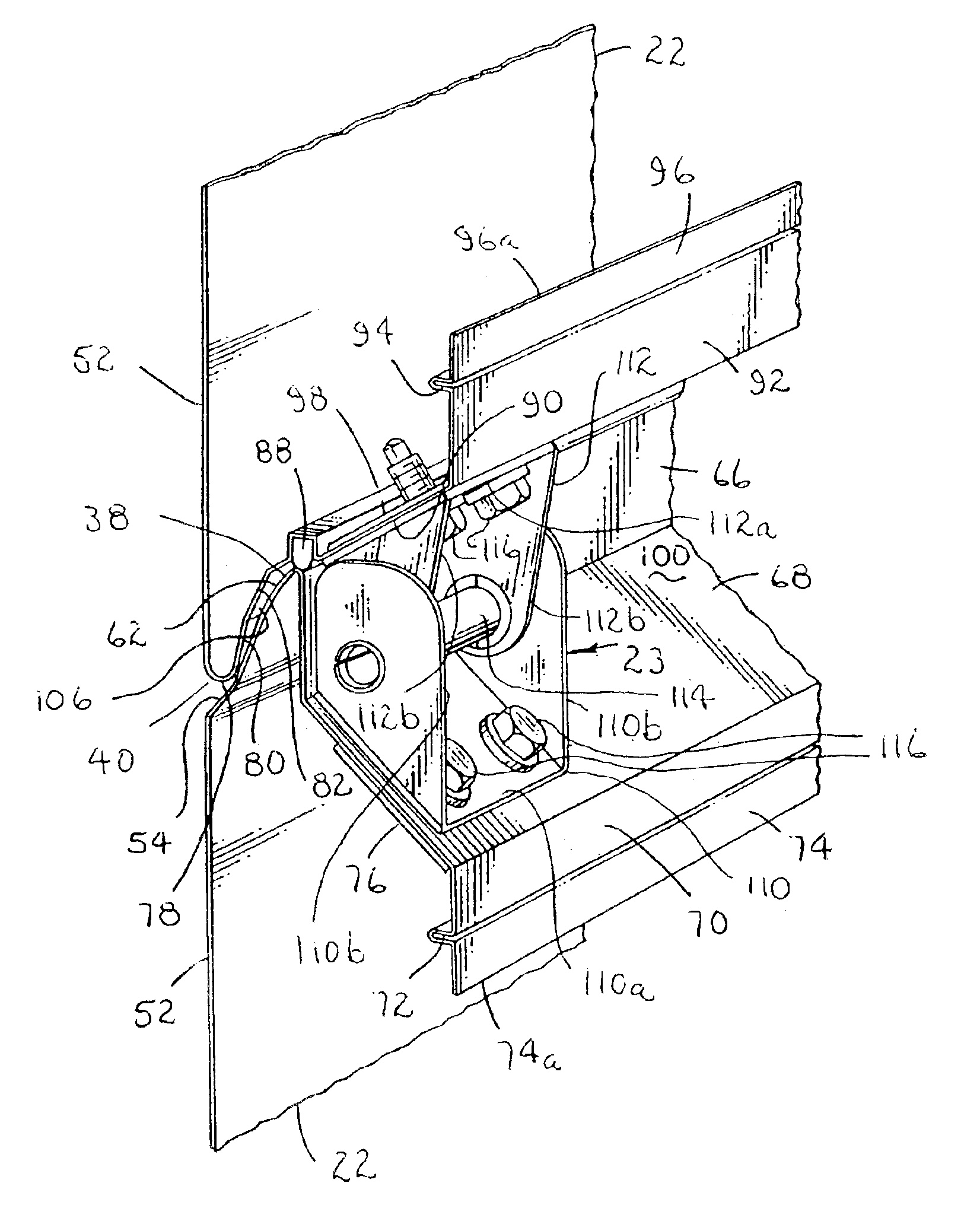
[0010]In accordance with another aspect of the present invention, a sectional upward acting door is provided which includes improved hinge assemblies for interconnecting the adjacent door panels, which hinge assemblies are adapted to cooperate with the door panels to be disposed substantially within a channel or trough space formed between adjacent panels when the door is in a closed position to eliminate projection of the hinge assemblies from the inner side or plane of the door panels.
[0012]Still further, the present invention provides an improved sectional or multipanel garage door and the like which includes hinge assemblies which may be easily snapped or pushed together and also includes improved door guide member support brackets which may also be quickly assembled to a door panel by a snap-in or push-in type motion to assemble the guide member support brackets to structural members of a door panel. In this way the door panels may be assembled substantially laterally with respect to the door guide tracks which receive the aforementioned guide members. Accordingly, an improved door assembly method is also provided which avoids a requirement to preassemble the guide member support brackets to the door panels, thus providing for easier packing and shipping. Moreover, the door panels do not require to be assembled by lifting the panels into positions required by prior art door panels with preassembled guide member support brackets and which must be connected to the guide tracks by inserting the door panels into the horizontal overhead run portion of the guide tracks. Accordingly, the door panels being fitted to a door opening may be assembled by stacking the panels vertically or inserting the panels through the horizontal sections of the guide tracks, if desired. A major advantage of the configuration of the improved sectional door is that the door panels no longer require that the hinge components be fastened to the panels after they have been put in place adjacent each other in the door opening or in the overhead horizontal run portion of the guidetracks.

Problems solved by technology

Another problem which has not been satisfactorily solved by prior art sectional door designs is the provision of a panel configuration, with or without a pinch resistant edge profile, which also provides for minimizing or eliminating hinge parts which project from the plane of the inner side of the door panel.

Method used


Image

  • Method of assembly of an upward acting sectional door
  • Method of assembly of an upward acting sectional door
  • Method of assembly of an upward acting sectional door

Examples


Embodiment Construction

[0040]In the description which follows, like parts are marked throughout the specification and drawing with the same reference numerals, respectively. The drawing figures may not necessarily be to scale and certain features of the invention may be shown in generalized form in the interest of clarity and conciseness.

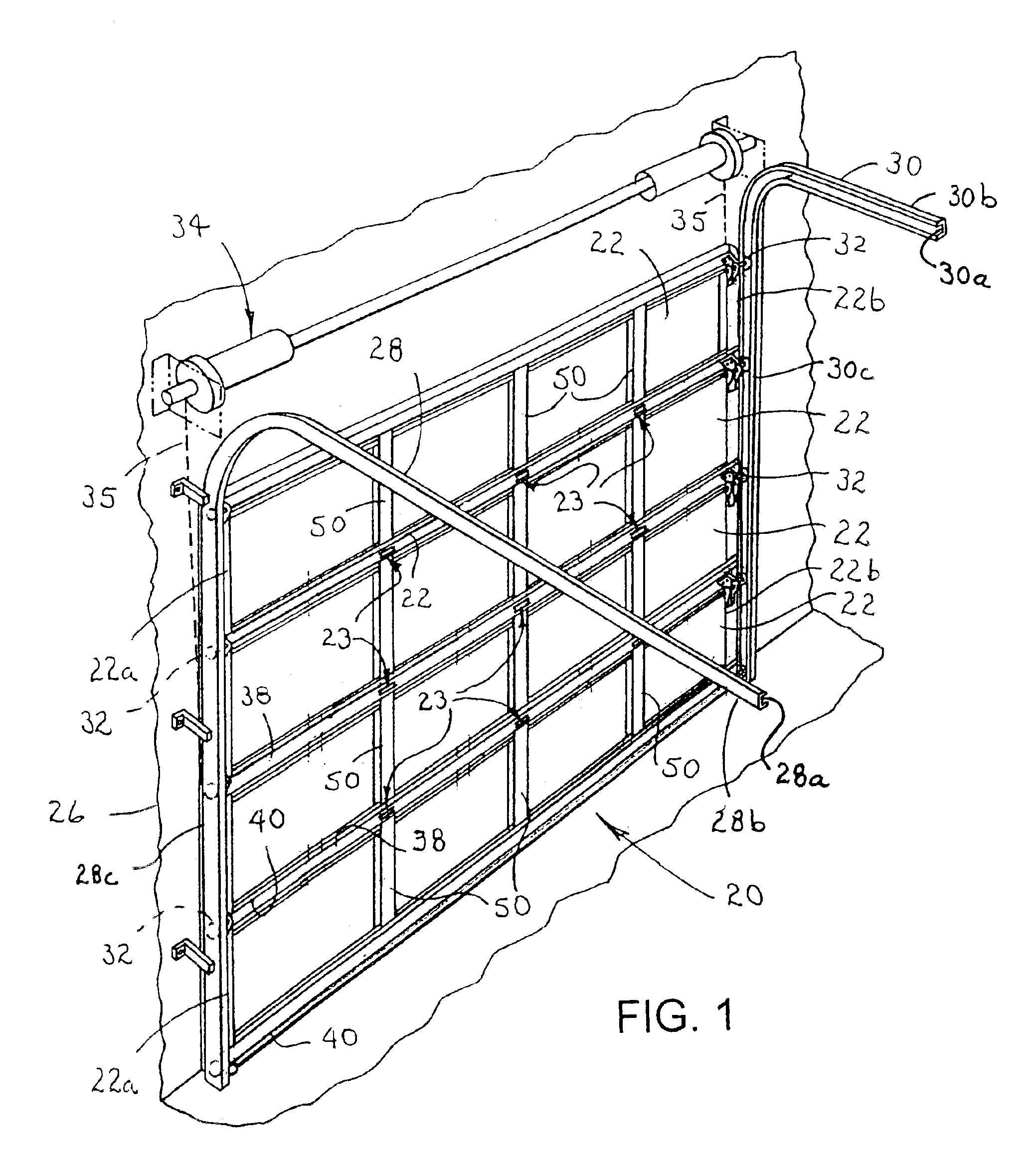
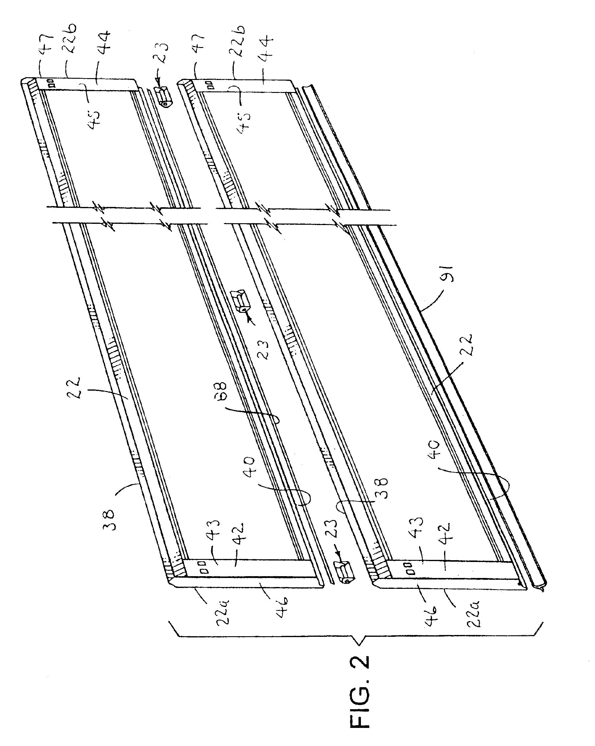
[0041]Referring to FIG. 1, there is illustrated a sectional upward acting door in accordance with the invention and generally designated by the numeral 20. The door 20 comprises a plurality of interconnected, generally planar door panels 22 which are configured to have edge profiles which cooperate with each other between adjacent door panels to provide for minimizing pinching of a person's fingers, for example, when the door panels are moved relative to each other between open and closed positions of the door. The door panels 22 are interconnected by improved hinge assemblies in accordance with the invention, one embodiment of which is illustrated in FIG. 1 and designate...


PUM

PropertyMeasurementUnit
Displacementaaaaaaaaaa

Abstract

A method of assembling a sectional upward acting door comprising plural generally planar door panels adapted to be guided between opposed guide tracks. The door panels are provided with hinge assemblies including a hinge plate mounted on the upper edge of one door panel with a pin receiving bore and a cooperating hinge plate with a hinge pin formed thereon mounted on the lower edge of the adjacent panel. One panel may be placed between the guide tracks and suitably supported while the next panel is assembled to the already positioned panel by placing the next panel between the guide tracks and moving it vertically downward to engage the hinge plates on the respective panels. The cooperating hinge plates are configured for snap together engagement which may only be released by intentional manipulation of the hinge plate with the pin receiving bore.

Description

CROSS REFERENCE TO RELATED APPLICATION[0001]This application is a division of application Ser. No. 10 / 046,363, filed Oct. 29, 2001, now U.S. Pat. No. 6,626,226 issued Sep. 30, 2003, which is a division of application Ser. No. 09 / 570,618 filed May 15, 2000, now U.S. Pat. No. 6,328,091 issued Dec. 11, 2001.FIELD OF THE INVENTION[0002]The present invention pertains to an upward acting multipanel or sectional door with pinch resistant edge profiles between the door panels and wherein the panels are interconnected by hinge assemblies which may be snapped together to facilitate assembly of the door.BACKGROUND[0003]Multipanel or so-called sectional garage doors and the like have been developed with panel edge profiles between adjacent door panels which are adapted to minimize pinching a person's fingers between the panels when the door moves to a closed position. Although various configurations of door panels with pinch resistant edge profiles are known in the prior art, there has been a c...

Claims


Application Information

Patent Timeline
IPC IPC(8): E05D15/24E05D15/16E06B7/23E06B3/32E06B3/48E06B7/22E05D7/00E05D7/10E05F7/00E06B7/36E06B9/02E06B9/15
CPCE05D7/1077E05D15/24E05D15/242E06B3/485E06B7/2301Y10T16/558E05D15/165E05Y2800/41E05Y2900/106E05Y2900/516Y10T16/53615Y10T16/5357Y10T16/525Y10T16/381E05D13/1261
Inventor WHITLEY, L. BLAKE
Owner OVERHEAD DOOR
Learn More