Tape threading mechanism

a technology of threading mechanism and tape, which is applied in the field of tape threading mechanism, can solve the problems of increasing the cost of the threading mechanism, the inability to read or write predetermined information from or write to the magnetic tape, and the inability to take up magnetic tape, etc., and achieves the effect of suppressing the increase in the cost of the mechanism per se and simplifying the configuration

Inactive Publication Date: 2005-04-26
NEC CORP
View PDF10 Cites 5 Cited by
  • Summary
  • Abstract
  • Description
  • Claims
  • Application Information

AI Technical Summary

Benefits of technology

[0024]With this configuration, it is possible to reliably move the leader block to the take-up center of

Problems solved by technology

However, the prior art has been disadvantageous as described below: first, since the turning variation is increased in order to correct the orientation of the leader block, it has taken too much time for a threading operation; second, since the trajectory of the threading pin draws a complicated curve, it has been necessary to configure the threading arm of two pieces of complicated link mechanisms in order to satisfy such a complicated trajectory; and third, in view of the above-described second disadvantage, since the two threading arms can be freely rotated with

Method used


Image

  • Tape threading mechanism
  • Tape threading mechanism
  • Tape threading mechanism

Examples


Embodiment Construction

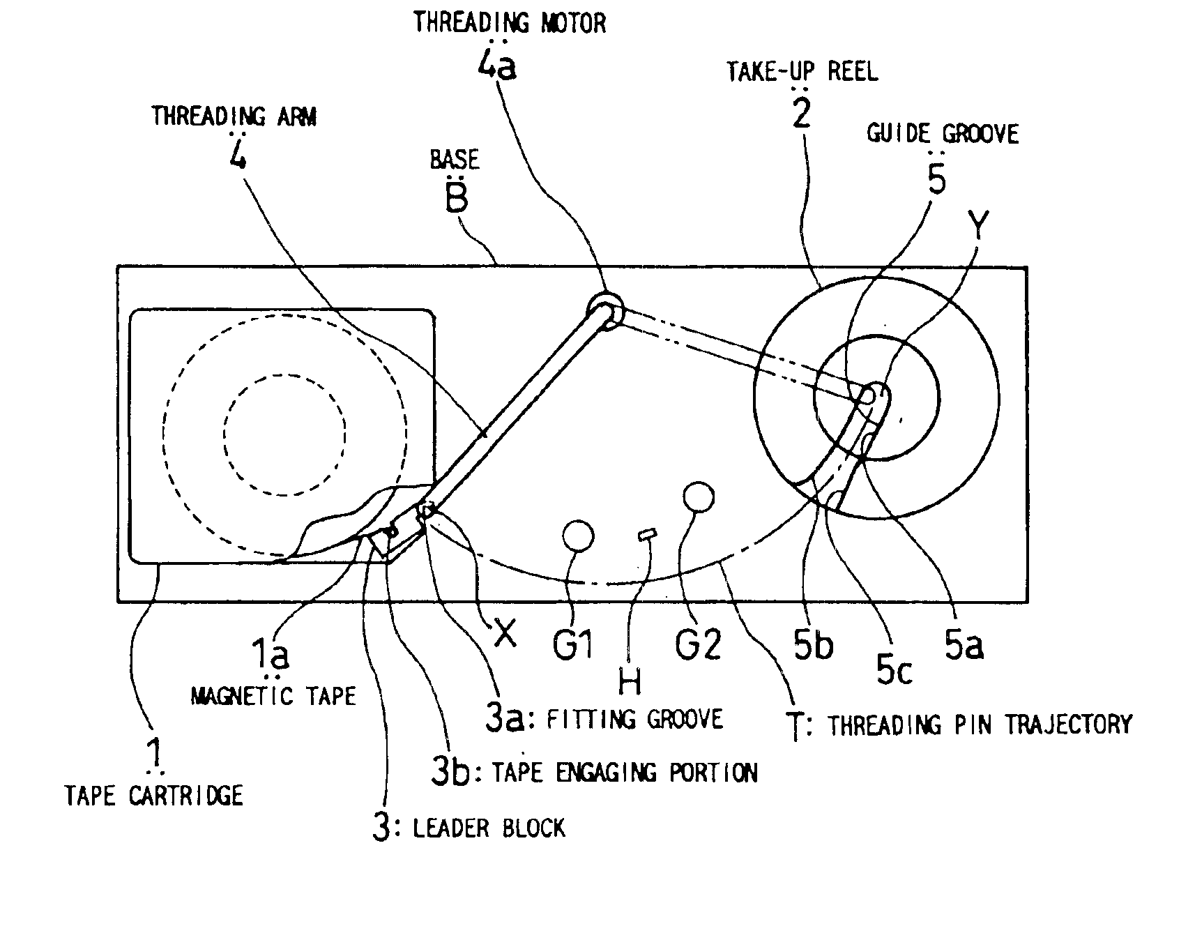
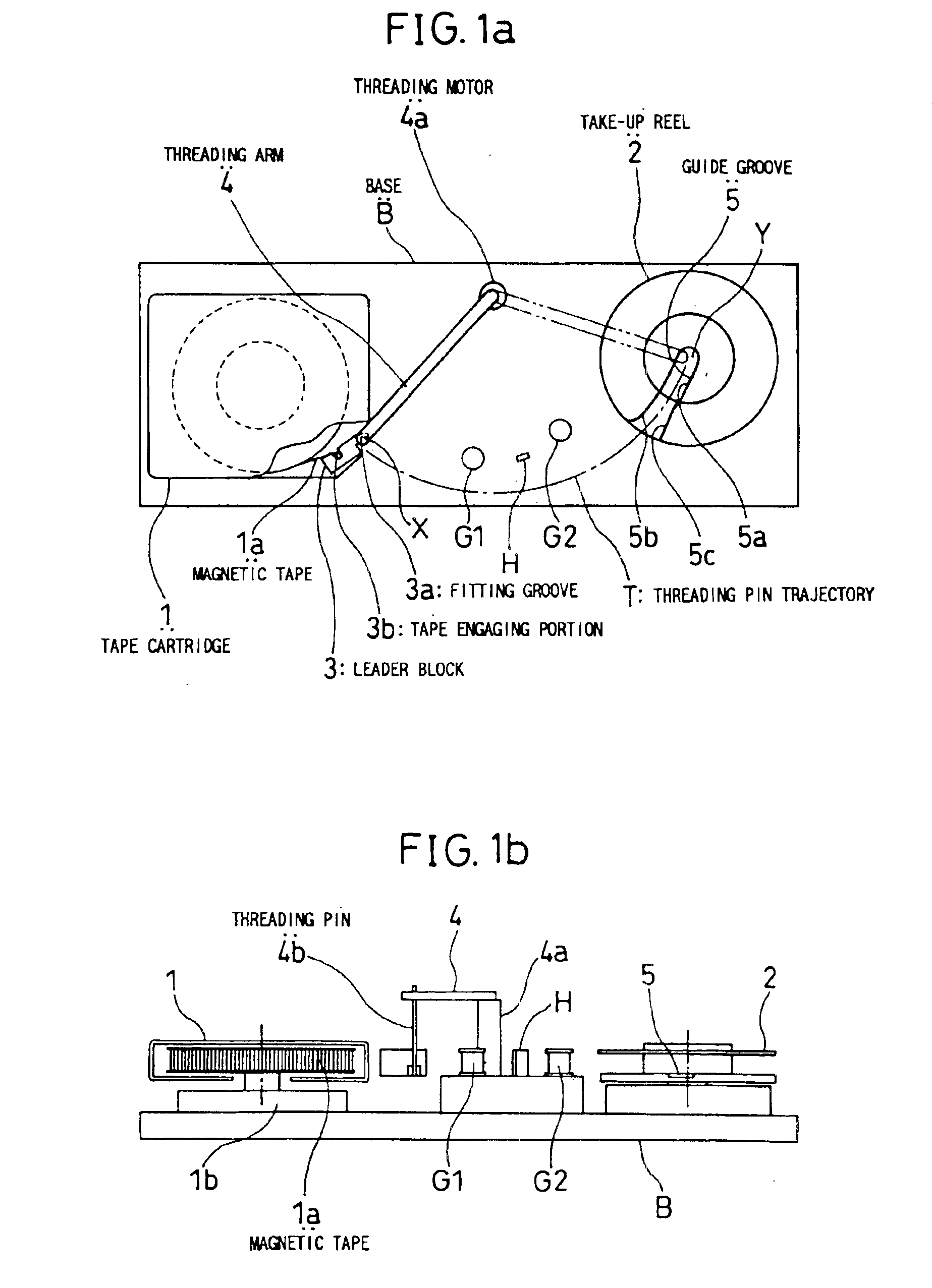
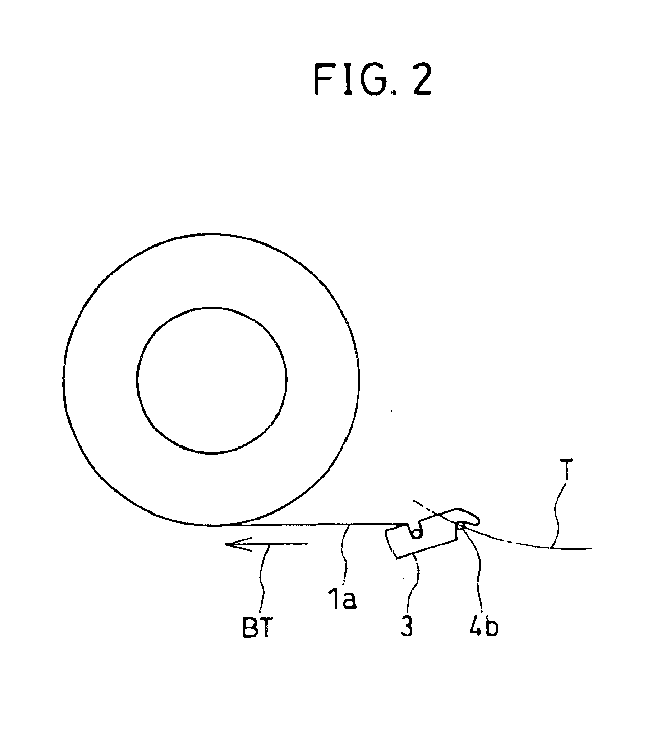
[0033]A tape threading mechanism in one preferred embodiment according to the present invention will be described below in reference to FIGS. 1 to 4. FIG. 1(a) is a plan view showing the configuration of a tape threading mechanism, and FIG. 1(b) is a schematic view of the mechanism as viewed from the front. The tape threading mechanism according to the present invention is incorporated inside of a magnetic tape device, and is adapted to move a leader block fixed to the tip of a magnetic tape to a take-up reel, so as to take up the magnetic tape housed inside of a tape cartridge by means of the take-up reel.

[0034]As shown in FIG. 1(a), the tape threading mechanism according to the present invention comprises a tape cartridge 1, in which a magnetic tape 1a is wound, a take-up reel 2 for taking up the magnetic tape 1a, a leader block 3 being fixed to the tip of the magnetic tape 1a and having a predetermined length; and a threading arm 4, which can turn, for moving the leader block 3 t...


PUM


Abstract

In a tape threading mechanism having a threading arm for moving a leader block from a tape cartridge to a take-up reel, the take-up reel is provided with a guide groove having an intrusion port in the vicinity of the outer periphery of the take-up reel so as to guide a leader block toward the take-up center of the take-up reel. One of side walls of the guide groove, against which the tip of the leader block abuts when the leader block intrudes into the guide groove, is formed in such a manner that the leader block can smoothly move into the take-up-center of the take-up reel.

Description

BACKGROUND OF THE INVENTION[0001]1. Field of the Invention[0002]The present invention relates to a tape threading mechanism and, more particularly, to a tape threading mechanism, which is provided in a magnetic tape device, for guiding the tip of a magnetic tape in a tape cartridge to the center of a take-up reel for taking up the magnetic tape.[0003]2. Description of the Related Art[0004]In a magnetic tape device as shown in FIG. 5(a) and 5(b), a tape threading mechanism has been conventionally used in which the tip of a magnetic tape 101a is drawn out of a tape cartridge 101, and then, is moved to the center of a take-up reel 102 for taking up the magnetic tape 101a. The tape threading mechanism in the prior art will be explained below in reference to FIGS. 5 to 7.[0005]FIGS. 5(a) and 5(b) are views showing the configuration of a tape threading mechanism in the prior art, wherein FIG. 5(a) is a plan view showing the configuration of the tape threading mechanism and FIG. 5(b) is a ...

Claims


Application Information

Patent Timeline
IPC IPC(8): G11B15/665G11B15/67
CPCG11B15/665G11B15/674G11B15/67
Inventor OJIMA, KENICHI
Owner NEC CORP
Why Eureka
Try Eureka