
Apparatus and method for maintaining constant drop volumes in a continuous stream ink jet printer

a technology of ink jet printer and drop volume, which is applied in the field of continuous stream ink jet printers, can solve the problems of adversely affecting system performance, adversely affecting print quality, and drop deflection mechanism may not consistently deflect drops

Inactive Publication Date: 2005-04-26
EASTMAN KODAK CO
View PDF27 Cites 22 Cited by
  • Summary
  • Abstract
  • Description
  • Claims
  • Application Information

AI Technical Summary

Benefits of technology

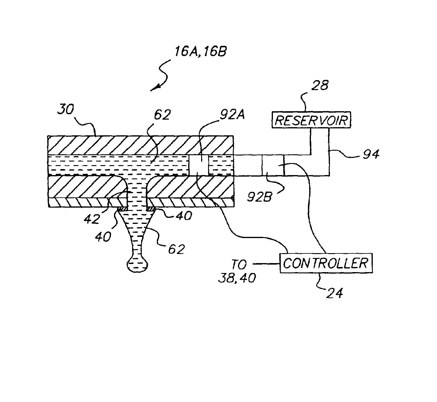
[0008]A method of maintaining an ejected ink drop volume in a continuous inkjet printer includes determining a change in an ink parameter; and varying a time period between activation control signals provided to an ink drop forming mechanism in response to the change in the ink parameter.
[0009]An apparatus for continuously ejecting ink includes a printhead. Portions of the printhead define a delivery channel and a nozzle bore with the delivery channel and nozzle bore defining an ink flow path. A drop forming mec

Problems solved by technology

Variations in drop volume can cause the printed dot size on the recording media to vary which can adversely affect print quality.
Additionally, variations in drop volume can adversely affect system performance.
For example, the drop deflection mechanism may not consistently deflect drops when the drop volume varies.
This can result in an increase or a decrease in the deflection angle causing drops to be deflected too much or not enough.
The extra ink provided by the drop forming mechanism degrades the print quality by causing an increase in the density of the printed dot.
Alternatively, the drop forming mechanism can provide drops having a smaller undesired volume when the surrounding temperature decreases which can also degrade print quality.
Again, this produces a variation in drop volume which can adversely affect print quality.
In these situations, adding solvent or ink concentrate to the ink composition to compensate for the temperature induced viscosity changes produces an ink composition having unintended property changes, for example changes in optical density and, as such, is an inadequate solution to the problem.
However, this solution is disadvantaged in that it requires additional hardware for the heating and / or cooling the ink which increases the cost of the printer.

Method used


Image

  • Apparatus and method for maintaining constant drop volumes in a continuous stream ink jet printer
  • Apparatus and method for maintaining constant drop volumes in a continuous stream ink jet printer
  • Apparatus and method for maintaining constant drop volumes in a continuous stream ink jet printer

Examples


Embodiment Construction

[0023]The present invention will be directed in particular to elements forming part of, or cooperating more directly with, apparatus in accordance with the present invention. It is to be understood that elements not specifically shown or described may take various forms well known to those skilled in the art.

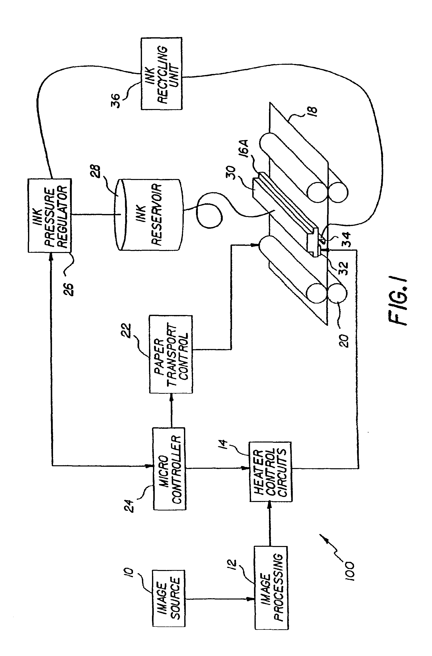
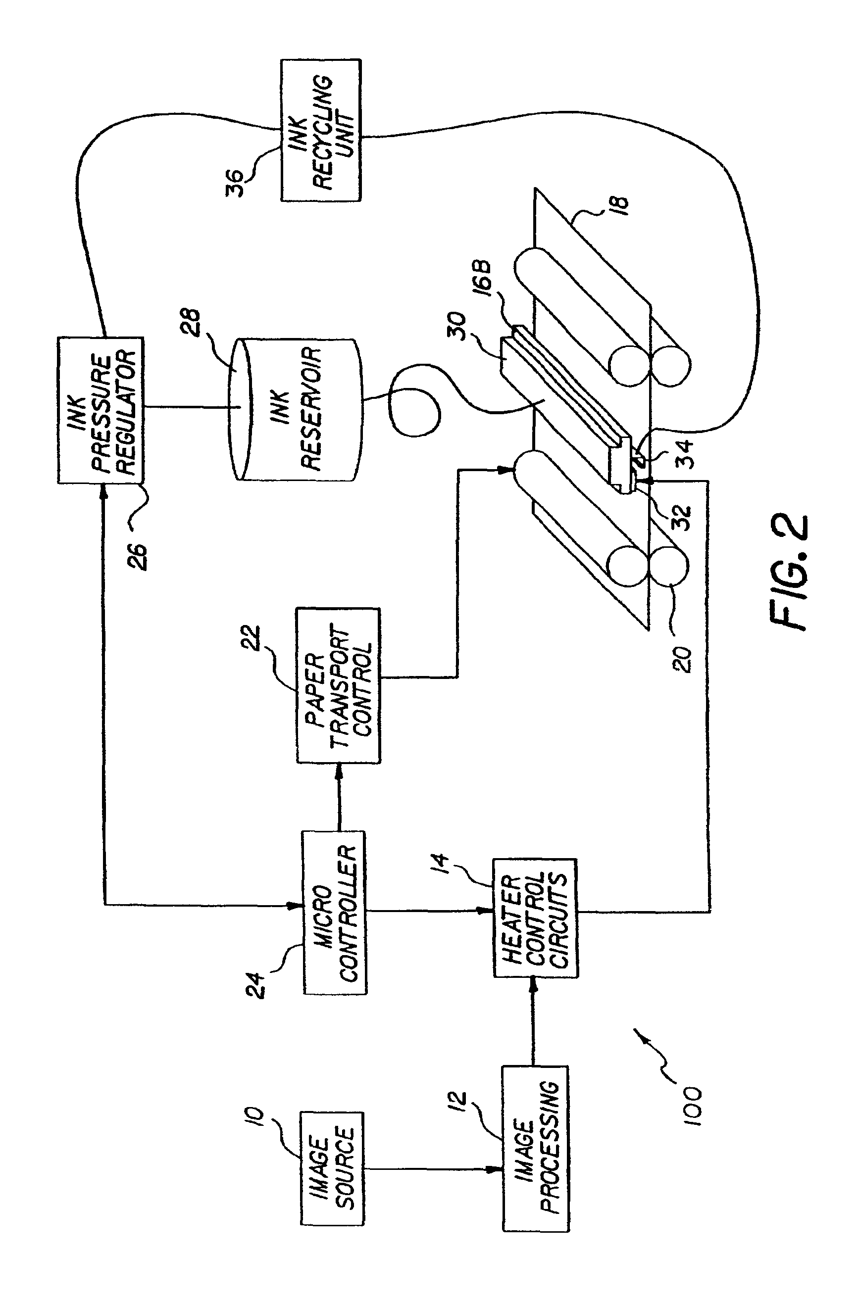
[0024]Referring to FIGS. 1 and 2, a continuous ink jet printer system 100 incorporating the present invention is shown. The system 100 includes an image source 10 such as a scanner or computer which provides raster image data, outline image data in the form of a page description language, or other forms of digital image data. This image data is converted to half-toned bitmap image data by an image processing unit 12, which also stores the image data in memory. A heater control circuit 14 reads data from the image memory and applies electrical pulses to a heater 32 that is part of a printhead 16A or a printhead 16B. These pulses are applied at an appropriate time, so that drops f...


PUM


Abstract

A method an apparatus for maintaining a predetermined ejected ink drop volume in a continuous inkjet printer is provided. An ink parameter, for example, temperature, velocity, flow rate, viscosity, is monitored. A time period between activation control signals provided to an ink drop forming mechanism is varied in response to a change in the ink parameter. The apparatus includes an ink parameter monitoring device which provides an input signal to a controller. The controller varies the time period between activation control signals provided to the ink drop forming mechanism.

Description

FIELD OF THE INVENTION[0001]The present invention relates generally to ink jet printers, and more particularly to compensating for inconsistencies in ejected drop volumes.BACKGROUND OF THE INVENTION[0002]Continuous ink jet (also commonly referred to as continuous stream, etc.) printing systems, use a pressurized ink source and a drop forming mechanism for producing a continuous stream of ink drops. Conventional continuous ink jet printers utilize electrostatic charging devices that are placed close to the point where a filament of working fluid breaks into individual ink drops. The ink drops are electrically charged and then directed to an appropriate location by deflection electrodes having a large potential difference. For example, when no printing is desired, the ink drops (non-printed drops, etc) are deflected into an ink capturing mechanism (catcher, interceptor, gutter, etc.) and either recycled or discarded while non-deflected ink drops (printed drops, etc.) are permitted to ...

Claims


Application Information

Patent Timeline
IPC IPC(8): B41J2/125B41J2/03B41J2/015B41J2/09B41J2/075
CPCB41J2/03B41J2/09B41J2/125B41J2002/033B41J2002/022B41J2002/031
Inventor JEANMAIRE, DAVID L.CHWALEK, JAMES M.
Owner EASTMAN KODAK CO
Learn More