Automotive laser illumination module and system

a laser illumination module and laser technology, applied in the direction of fixed installation, lighting and heating equipment, instruments, etc., can solve the problems of increasing reducing the visibility of the vehicle, and reducing the visibility of the atmosphere, so as to improve reduce the difficulty of seeing, and the effect of enhancing the visibility of the vehicl

Inactive Publication Date: 2005-04-26
SARABIA MARIBEL
View PDF10 Cites 35 Cited by
  • Summary
  • Abstract
  • Description
  • Claims
  • Application Information

AI Technical Summary

Benefits of technology

[0009]It is an object of the invention to produce an automotive laser illumination module that is effective at enhancing the visibility of a vehicle. Accordingly, the module creates, controls, and directs a beam of laser light from the vehicle such that it is more easily seen than conventional automotive lights, especially during times of decreased atmospheric visibility.
[0010]It is another object of the invention to enhance manufacturing efficiency by providing an automotive laser illumination module that can be used as a headlight or taillight. Accordingly, the module is switchable between headlight and taillight modes.

Problems solved by technology

Accordingly, the importance of making the vehicle visible to other vehicles and pedestrians cannot be discounted.
At times, however, conventional, halogen, and even xenon headlights are not successful in warning others of its presence, and its approach.
In addition, in certain conditions the headlights even make it more difficult to see.
Unfortunately, under severe weather conditions many of these lights decrease visibility for the driver.

Method used


Image

  • Automotive laser illumination module and system
  • Automotive laser illumination module and system
  • Automotive laser illumination module and system

Examples


Embodiment Construction

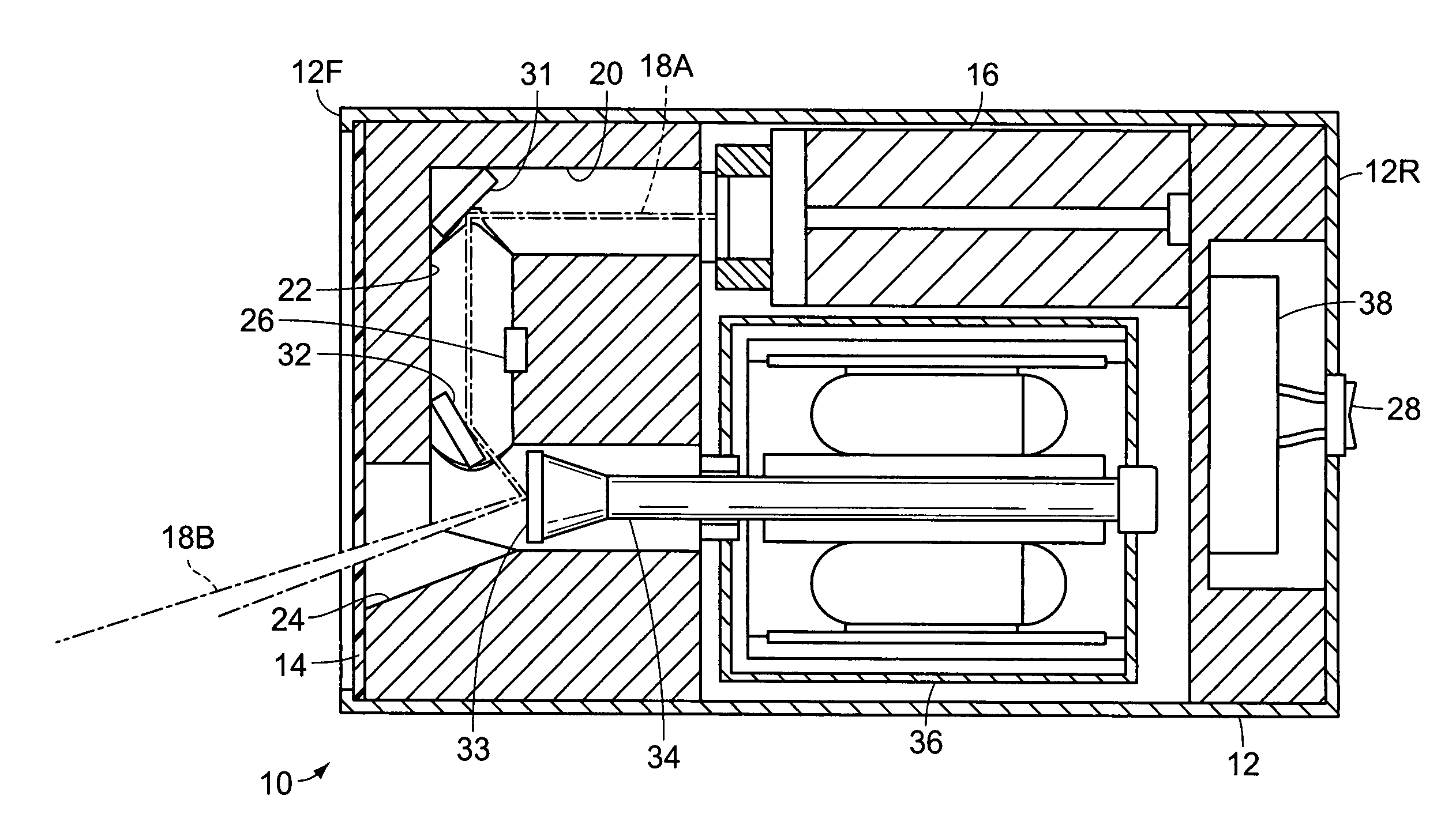
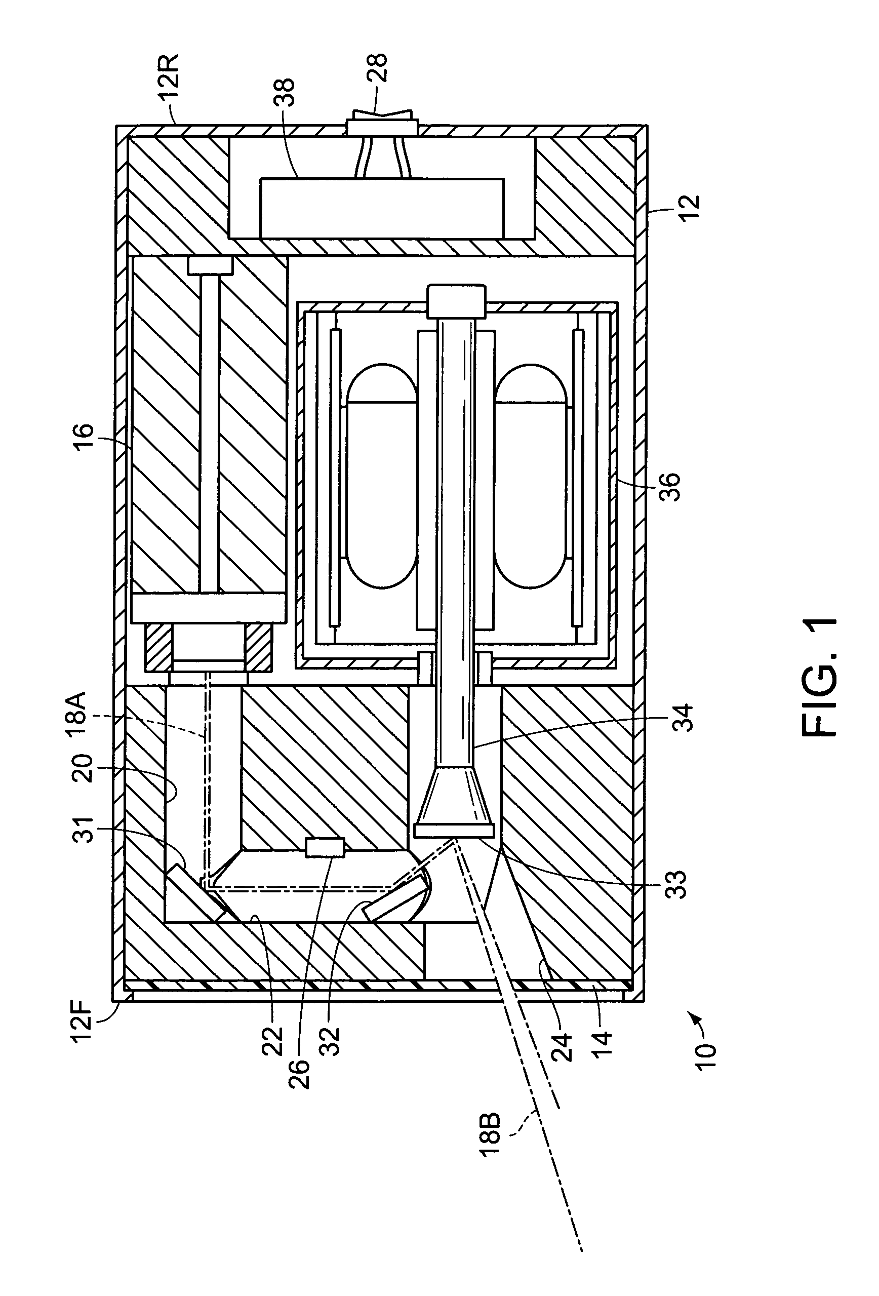
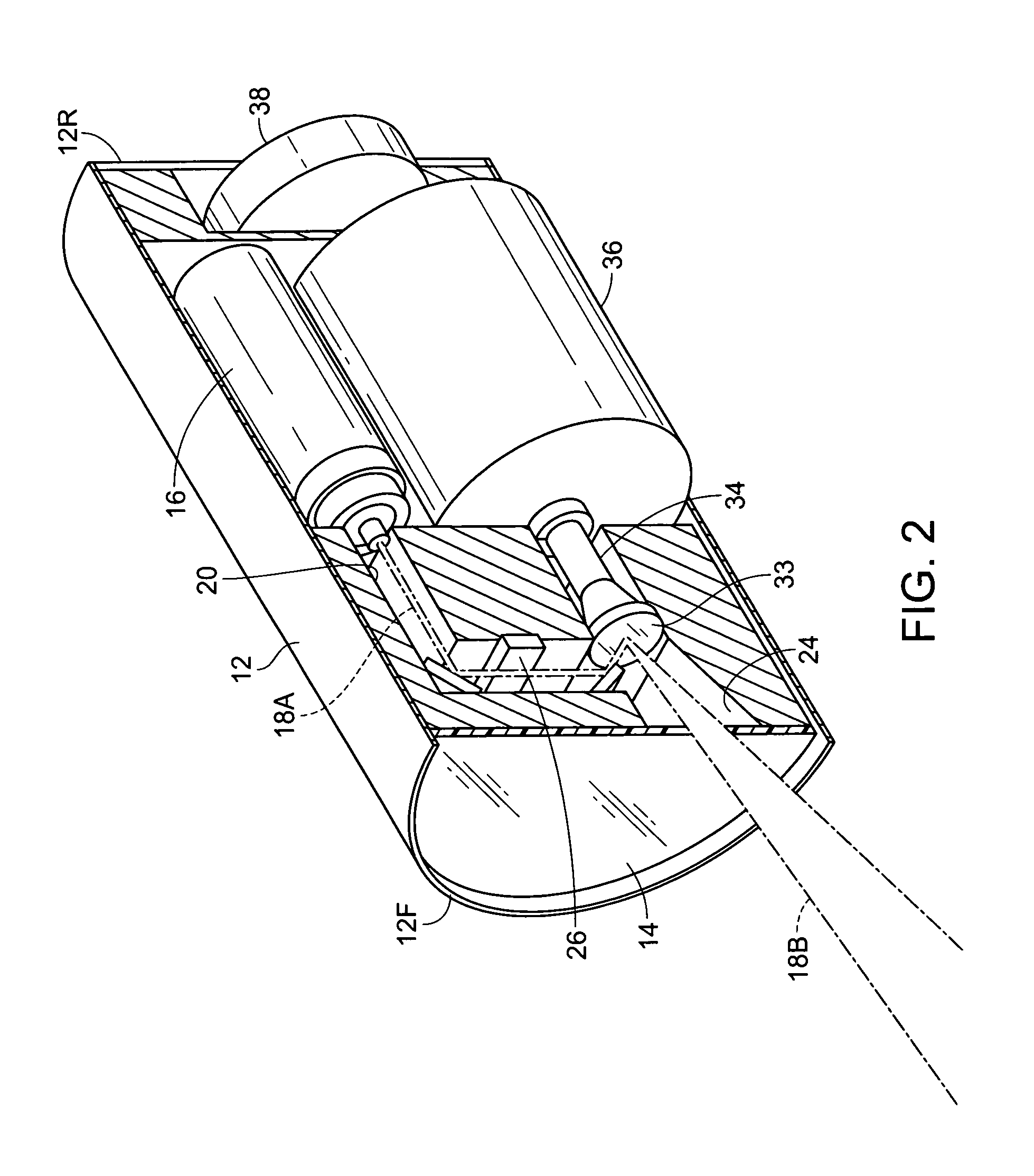
[0023]FIGS. 1 and 2 illustrates a laser module 10, per se, which forms a portion of a laser illumination system of the present invention. The laser module 10 has an outer housing 12, having a front 12F and a rear 12R. A lens 14 is located at the front 12F. The lens is essentially transparent, and may be a planar—allowing light to pass therethrough without diffraction or diversion, or may be configured as partially or fully convex or concave to alter light traveling therethrough.

[0024]Within the housing 12, a beam emitter 16 is provided to produce an initial beam of laser light 18A, which is substantially monochromatic and coherent. The beam emitter 16 can be provided using a variety of different technologies, such as using gas filled tubes such as a HeNe (Helium-Neon) or CO2 (Carbon Dioxide) laser tube, lasing rods such as ruby-rod or YAG rods which produce laser light upon the absorbtion of adjacent flash discharge tubes, or can be diode based. Diode based lasers are typically less...


PUM


Abstract

A laser illumination system, for use with an automobile, comprising a plurality of modules. Each module has a housing having a lens, and a mode selection switch for choosing between headlight and taillight modes. Preferably, two modules are mounted at the front of the automobile to function as headlights, and two of the modules are mounted at the rear of the automobile to function as taillights. Each module has a beam emitter which produces an initial beam of laser light and an output mirror which directs an exit beam through the lens, outwardly of the automobile, and ultimately creates a cone of light at the ground surface forwardly or rearwardly of the automobile. When used as a headlight and the mode selection switch is appropriately set, an output mirror rotation motor spreads the output beam so that it creates a larger cone on the ground surface.

Description

BACKGROUND OF THE INVENTION[0001]The invention relates to an automotive laser illumination module and system. More particularly, the invention relates to an illumination module which is used to provide illumination external to an automobile for enhancing the visibility of the automobile to others, and a system for providing and controlling multiple illumination modules within the automobile.[0002]Automotive headlights serve two important purposes. First they help illuminate objects in front of the vehicle, so that the driver can best see and avoid any obstacles. In addition, they enhance the visibility of the vehicle, so that others can recognize that a vehicle is approaching, how quickly, and the trajectory upon which it is traveling.[0003]The second purpose for the headlights is actually more important. When traveling at highway speeds, the distance which can be adequately illuminated by the headlights is often considerably less than that distance within which the driver could st...

Claims


Application Information

Patent Timeline
Patent Type & Authority Patents(United States)
IPC IPC(8): F21S8/10B60Q1/28B60Q1/30
CPCB60Q1/28B60Q1/30F21S48/215F21S48/1159B60Q2400/50F21Y2101/025F21Y2101/02F21Y2115/30F21Y2115/10F21S43/14
Inventor SARABIA, MARIBEL
Owner SARABIA MARIBEL
Why Eureka
Try Eureka