Structural enclosed rotor configuration for electric machine

a rotor configuration and enclosed technology, applied in the direction of magnetic circuit rotating parts, magnetic circuit shape/form/construction, prevention/reduction of eddy current losses in winding heads, etc., can solve the problem of limited rotor size, especially the diameter

Inactive Publication Date: 2005-04-26
GENERAL ELECTRIC CO
View PDF21 Cites 20 Cited by
  • Summary
  • Abstract
  • Description
  • Claims
  • Application Information

AI Technical Summary

Problems solved by technology

The rotor size, especially the diameter, is limited by the material strength of the shaft and retaining rings.

Method used


Image

  • Structural enclosed rotor configuration for electric machine
  • Structural enclosed rotor configuration for electric machine
  • Structural enclosed rotor configuration for electric machine

Examples


Embodiment Construction

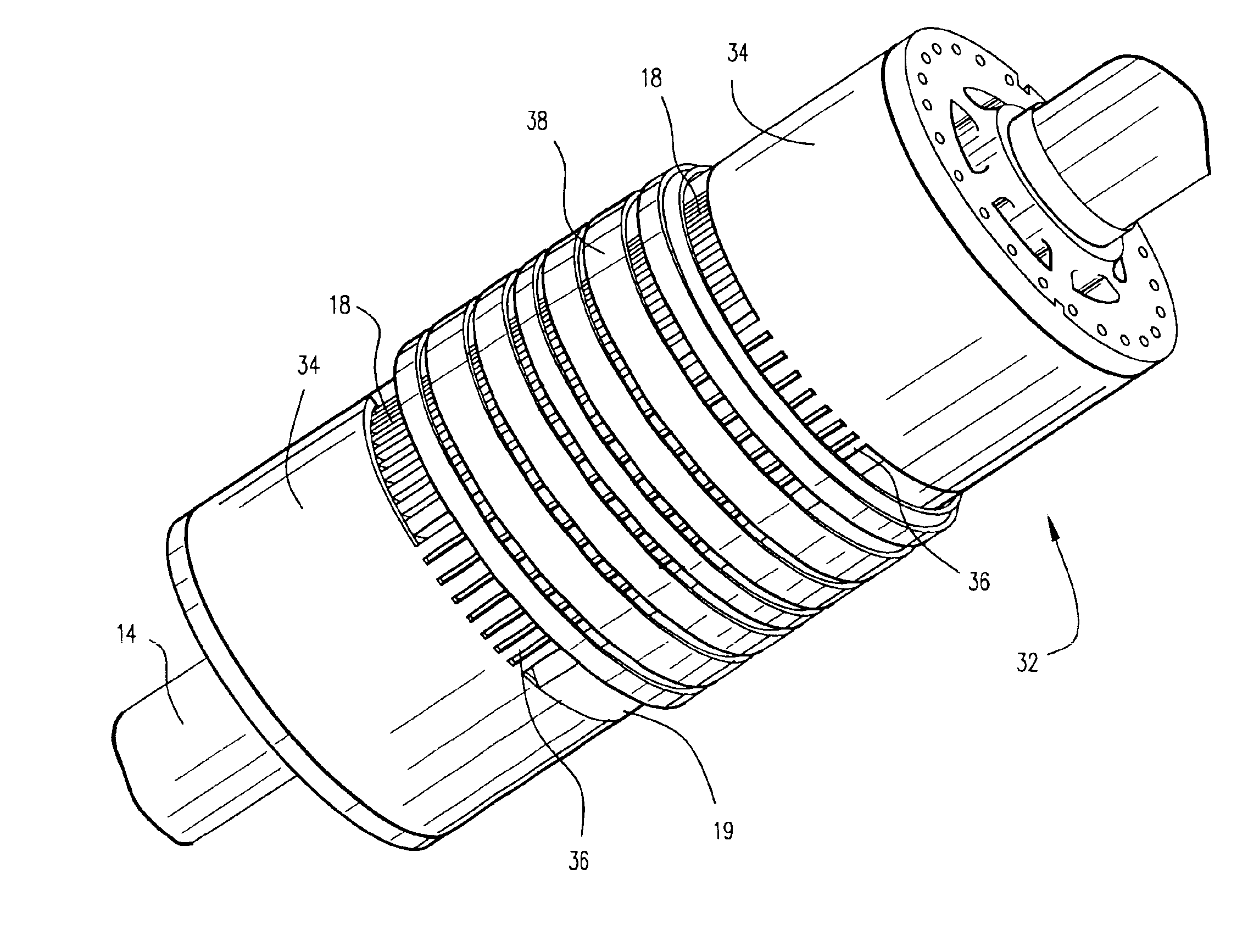
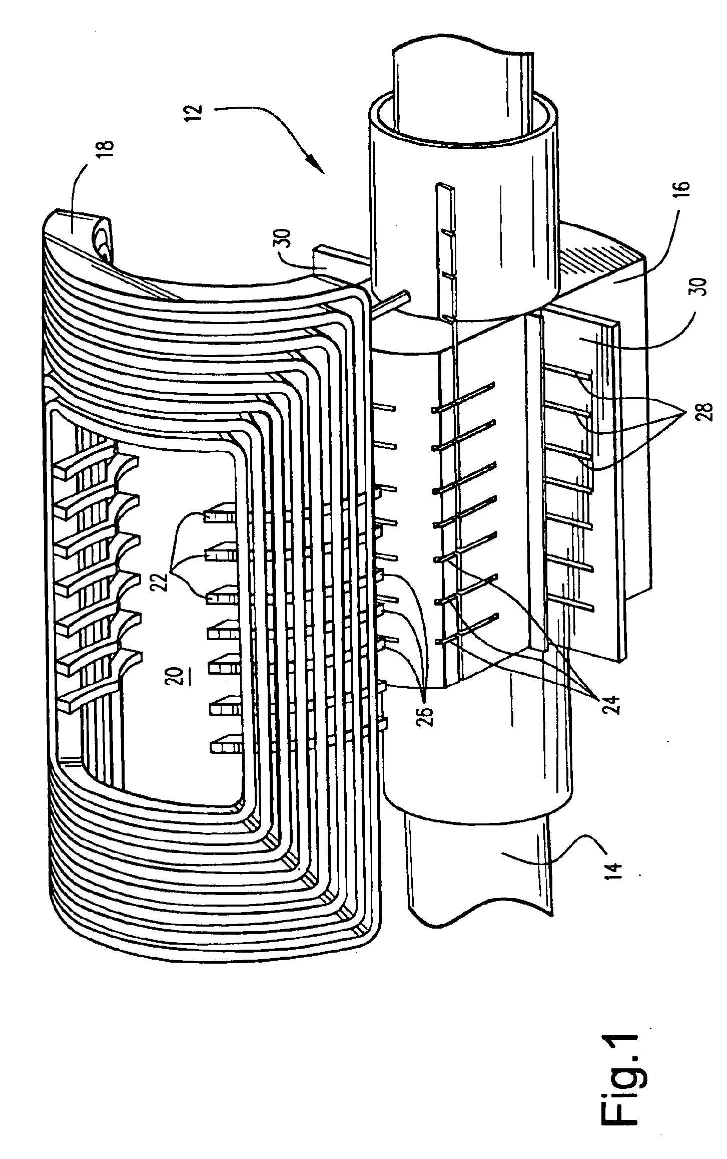
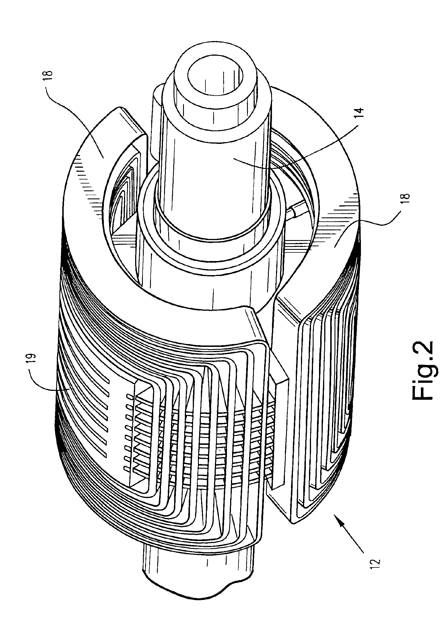
[0016]An assembled rotor configuration 10 for an electric machine such as a generator or the like is shown in FIG. 4. With reference to FIGS. 1 and 2, the rotor configuration 10 includes a rotor assembly 12 having a rotor shaft 14 and a multi-pole magnetic rotor core 16 secured to the rotor shaft 14. A two-pole core 16 is shown in FIG. 1. A plurality of field winding modules 18 are respectively disposed over each pole of the multi-pole rotor core 16. Each of the winding modules 18 includes an opening 20 therein for receiving each pole of the rotor core 16 such that the pole faces 19 of the rotor core 16 are exposed.

[0017]Generally, the construction and materials of the magnetic core 16 and field winding modules 18 are known, and details thereof will not be further described. With continued reference to FIGS. 1 and 2, the field winding modules 18 are provided with projections 22 extending into the opening 20, which projections 22 engage corresponding notches 24 in the rotor core 16. ...


PUM


Abstract

A rotor configuration for an electric machine includes a rotor shaft and a multi-pole rotor core secured to the rotor shaft. A plurality of field winding modules are respectively disposed over each pole of the multi-pole rotor core. An enclosure is disposed over the field winding modules for containing the field winding modules over the rotor core. A magnetic shield is disposed over the field winding modules between the field winding modules and the enclosure. The simplified construction reduces manufacturing time and costs.

Description

BACKGROUND OF THE INVENTION[0001]The present invention relates to a rotor configuration for an electric machine and, more particularly, to a rotor configuration including a magnetic shield member disposed between field winding modules and a rotor enclosure.[0002]In a conventional electric machine such as a generator having a rotor and a stator, the rotor is provided with field windings that excite the generator while receiving a current from an exciting current source. The stator is provided with armature windings from which electrical power is output. Typical rotor construction requires a field winding be assembled bar by bar, into radial slots milled into a rotor forging. Containment of the rotor field windings is typically achieved using rotor wedges, rotor teeth and retaining rings.[0003]As rotor wedges, conventional generator fields use axial slotted forgings to wedge in the copper field winding turn by turn. As a result, the significant mass of copper is strongly coupled with ...

Claims


Application Information

Patent Timeline
Patent Type & Authority Patents(United States)
IPC IPC(8): H02K3/00H02K3/42H02K3/50H02K3/51
CPCH02K3/42H02K3/51
Inventor KAMINSKI, CHRISTOPHER ANTHONYWANG, YU
Owner GENERAL ELECTRIC CO
Why Eureka
Try Eureka