Circuit and method for accurately applying a voltage to a node of an integrated circuit

a technology of integrated circuits and voltages, applied in the direction of electronic circuit testing, measurement devices, instruments, etc., can solve the problems of not providing a way of applying a high frequency voltage signal, unable to deliver the desired voltage to the circuit node of interest within the circuit, and not providing a way of accurately delivering a voltage

Inactive Publication Date: 2005-04-26
SIEMENS PROD LIFECYCLE MANAGEMENT SOFTWARE INC
View PDF15 Cites 34 Cited by
  • Summary
  • Abstract
  • Description
  • Claims
  • Application Information

AI Technical Summary

Benefits of technology

[0007]An objective of the present invention is to provide a method and a circuit for accurately delivering a voltage, DC or AC, to IC circuit nodes that have significant impedances to ground, via common buses and transmission gates that have significant series impedance.
[0008]A further objective of the present invention is to provide a method and a circuit for accurately delivering high frequency AC voltages to circuit nodes by applying a low frequency to a common bus and switching at a high frequency, at the circuit node, between a low frequency bus signal and some other signal.
[0011]One aspect of the present invention is generally defined as a method for accurately delivering a voltage to a circuit node of an integrated circuit having analog buses and transmission gates selectively connecting the circuit node to the buses, comprising: sensing the voltage on the circuit node via a first of the buses under control of a first periodic signal; applying a first stimulus voltage to the circuit node via a second bus under control of a second periodic signal; applying a second stimulus voltage to the circuit node under control of a third periodic signal which is inverted with respect to the second periodic signal so that the circuit node is driven alternately to the first stimulus voltage and to the second stimulus voltage.

Problems solved by technology

While these arrangements succeed in accurately delivering a desired voltage to an IC pin, it does not deliver the desired voltage to the circuit node of interest within the circuit.
More specifically, the arrangements do not accommodate voltage drops which may occur between the IC pin and the node of interest.
It also does not provide a way of applying a high frequency voltage signal.
If the transmission gates have significant series impedance, for example comparable to the impedance of the pull-up resistance of the pin, then the pin cannot be accurately driven to a stimulus voltage because of the unknown voltage drop across the transmission gate.
Saitoh is not concerned with and does not provide a method of accurately delivering a voltage to a circuit node within the circuit.

Method used


Image

  • Circuit and method for accurately applying a voltage to a node of an integrated circuit
  • Circuit and method for accurately applying a voltage to a node of an integrated circuit
  • Circuit and method for accurately applying a voltage to a node of an integrated circuit

Examples


Embodiment Construction

[0024]In the following detailed description, numerous specific details are set forth in order to provide a thorough understanding of the present invention, However, it will be understood by those skilled in the art that the present invention may be practiced without these specific details. In other instances, well known methods, procedures, components and circuits have not been described in detail so as not to obscure aspects of the present invention.

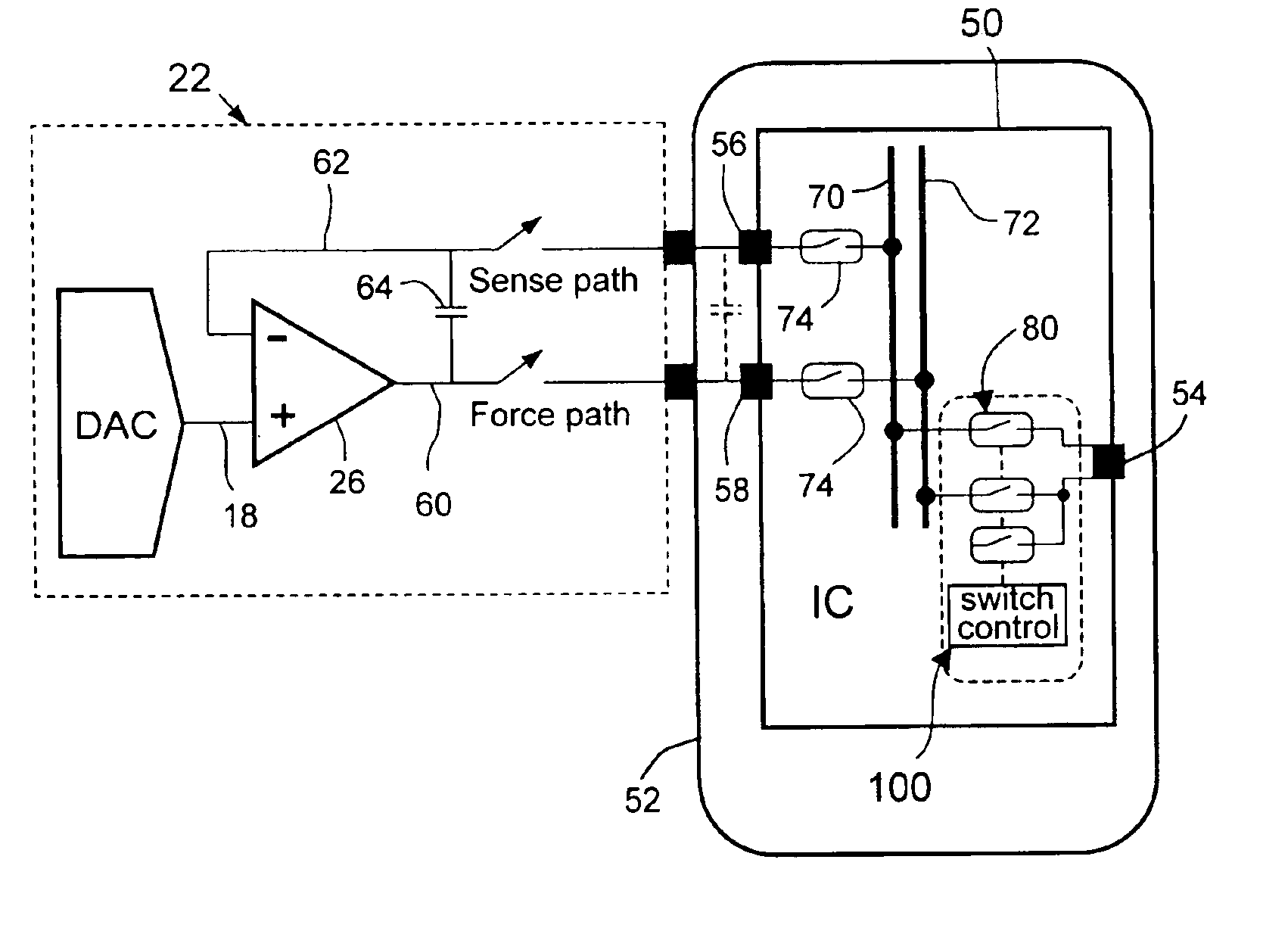
[0025]As mentioned earlier, a primary objective of the present invention is to accurately deliver a stimulus voltage to a circuit node, which may be a bond pad of an integrated circuit and which may have significant impedance to ground, via a common bus so that mechanical connection to the circuit node is unnecessary. A further objective is to provide means for accurately delivering a stimulus voltage that has a frequency that is too high for the common bus. Another objective is facilitating reduced pin count access to an IC during manu...


PUM


Abstract

A method for accurately delivering a voltage to a circuit node of an integrated circuit having analog buses and transmission gates selectively connecting the circuit node to the buses, comprises sensing the voltage on the circuit node via a first of the buses under control of a first periodic signal; applying a first stimulus voltage to the circuit node via a second bus under control of a second periodic signal; and applying a second stimulus voltage to the circuit node under control of a third periodic signal which is inverted with respect to the second periodic signal so that the circuit node is driven alternately to the first stimulus voltage and to the second stimulus voltage.

Description

CROSS-REFERENCE TO RELATED APPLICATIONS[0001]This application claims the benefit of U.S. Provisional Patent Application Ser. No. 60 / 410,270 filed Sep. 13, 2002.BACKGROUND OF THE INVENTION[0002]1. Field of the Invention[0003]The present invention generally relates to the design and testing of integrated circuits (ICs), and, more specifically, to a method and circuit for accurately delivering DC or AC voltage to circuit nodes of integrated circuits.[0004]2. Description of Related Art[0005]Automatic Test Equipment (ATE) typically includes a parametric measurement unit (PMU) to measure the drive of an output pin of an IC, or to accurately deliver a DC voltage to an IC pin. The output drive of a pin is tested by applying a known current to the pin and measuring the resultant voltage at the pin, or by applying a known voltage and measuring the resultant current. FIG. 1 shows a simple IC 10, having pins 12 and 14, mounted on a device interface board 16 associated with test equipment 22. A ...

Claims


Application Information

Patent Timeline
Patent Type & Authority Patents(United States)
IPC IPC(8): G01R31/28
CPCG01R31/2886G01R31/2841
Inventor SUNTER, STEPHEN K.
Owner SIEMENS PROD LIFECYCLE MANAGEMENT SOFTWARE INC
Why Eureka
Try Eureka