Filter using film bulk acoustic resonator and transmission/reception switch

a film bulk acoustic resonator and filter technology, applied in the field of communication devices, can solve the problems of small size of saw filter, insufficient satisfaction of the demand for the reduction of mounting area or height, and large loss of resonator, and achieve the effect of enhancing attenuation characteristics and enhancing attenuation characteristics

Inactive Publication Date: 2005-04-26
MEMS SOLUTIONS INC
View PDF12 Cites 36 Cited by
  • Summary
  • Abstract
  • Description
  • Claims
  • Application Information

AI Technical Summary

Benefits of technology

[0017]In an aspect of the present invention, the transmission band filter includes at least one inductor for enhancing attenuation characteristics on a higher frequency side than the transmission frequency pass band. In an aspect of the present invention, the inductor is connected in parallel with same of the first series elements. In an aspect of the present invention, one end of the inductor is connected to the transmission port.
[0018]In an aspect of the present invention, the reception band filter includes at least one capacitor for enhancing attenuation characteristics on a lower frequency side than the reception frequency pass band. In an aspect of the present invention, the capacitor is connected in parallel with some of the second series elements. In an aspect of the present invention, one end of the capacitor is connected to the reception port.

Problems solved by technology

On the other hand, since a size of the cellular phone is restricted, after all it is necessary to raise a mounting density in an apparatus.
The ceramic filter can be monolithic and is inexpensive, but a loss of a resonator is large.
To cover this, a dimension of about 23×7×5 mm is required, and the demand for the reduction of the mounting area or height cannot sufficiently be satisfied.
On the other hand, the SAW filter is small in size, but has a problem in the power handling capability at a high frequency, and there is a possibility that the filter breaks down, when a surge is generated in an output power of transmission.
However, in this case, the circuit constitution becomes complicated and expensive.
Therefore, for the duplexer described in the above JP(A) 2001-24476, a plurality of filters and 90-degrees phase shifter need to be mounted on one substrate, and it is difficult to constitute a monolithic structure and to sufficiently reduce the cost.
However, in this case, a length of at least ten or more millimeters is necessary, a considerably large space is required as compared with the filter, and this constitution is unsuitable for miniaturization.
That is, features of the film bulk acoustic resonator suitable for the miniaturization cannot sufficiently be utilized.
In this case, the required pass band width cannot easily be achieved.
However, this method has a defect that the inductor is attached to the film bulk acoustic resonator from the outside and accordingly the whole size of the filter increases.

Method used


Image

  • Filter using film bulk acoustic resonator and transmission/reception switch
  • Filter using film bulk acoustic resonator and transmission/reception switch
  • Filter using film bulk acoustic resonator and transmission/reception switch

Examples


Embodiment Construction

[0046]Embodiments of the present invention will hereinafter be described with reference to the drawings.

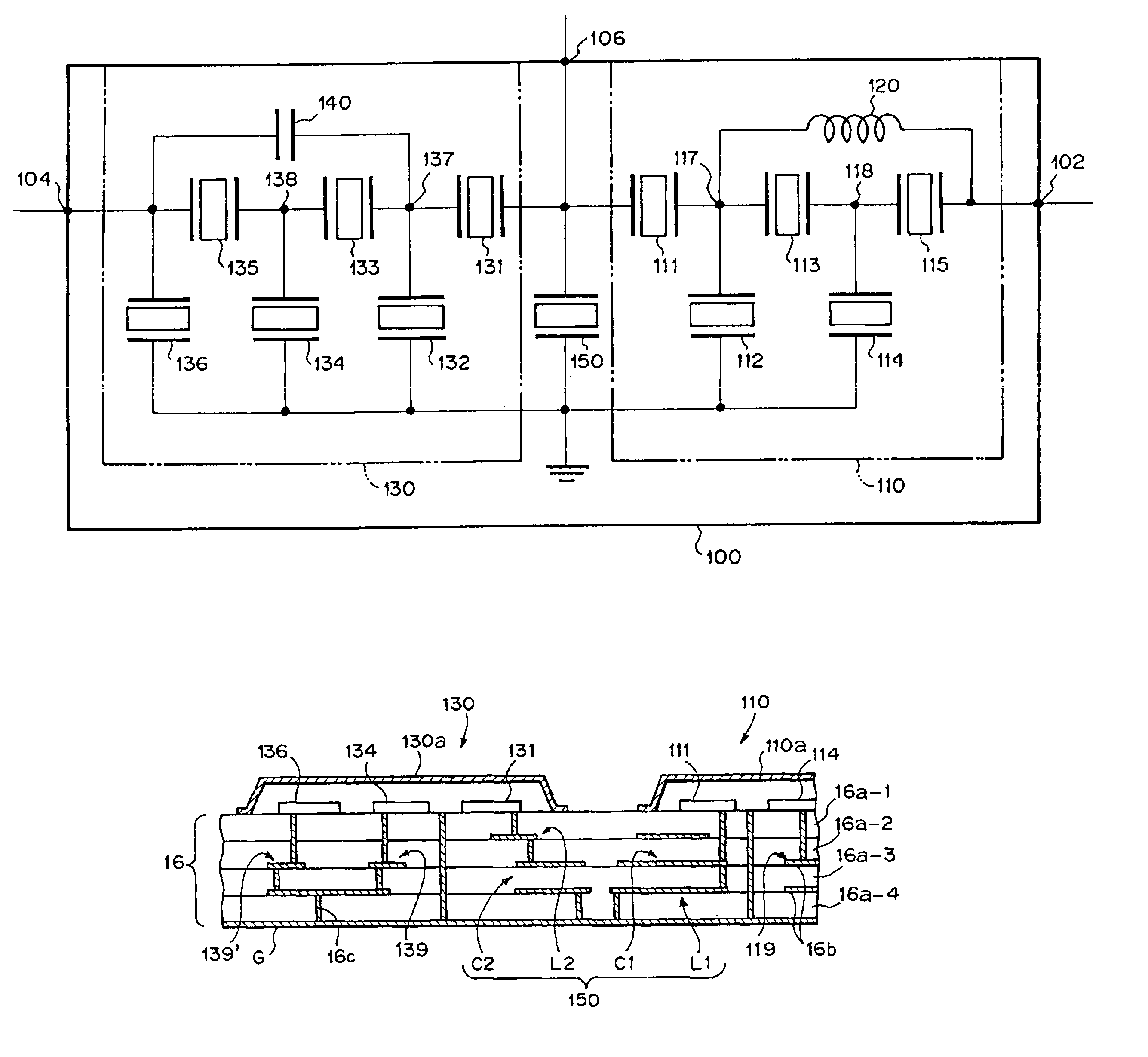
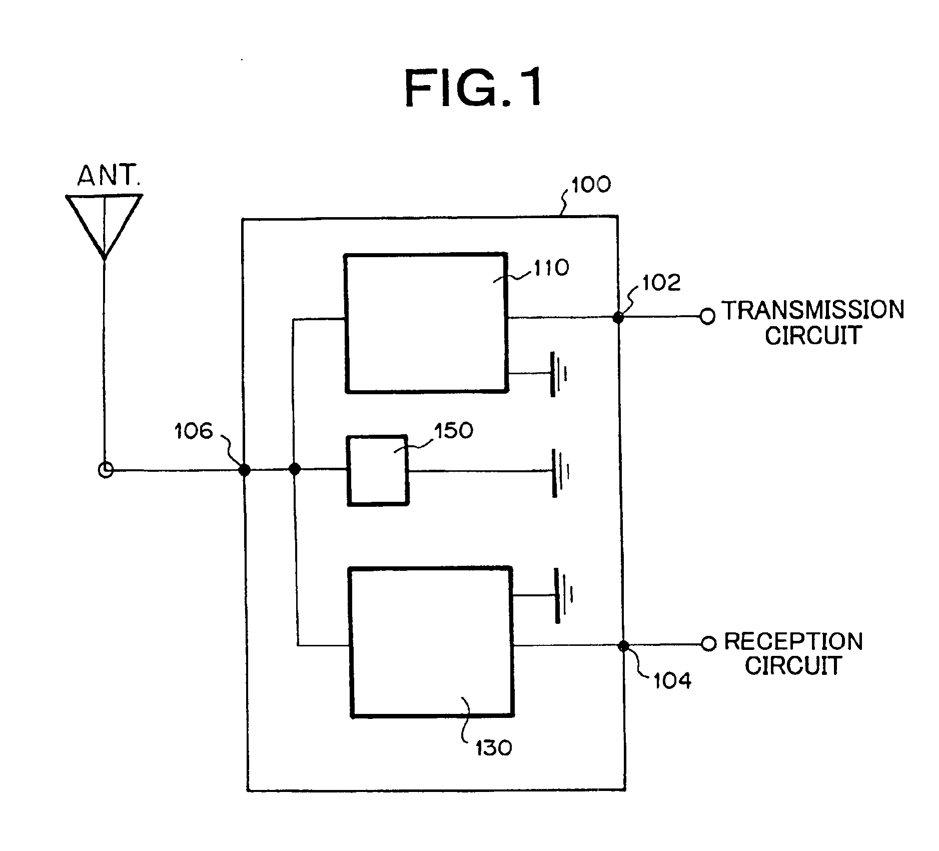
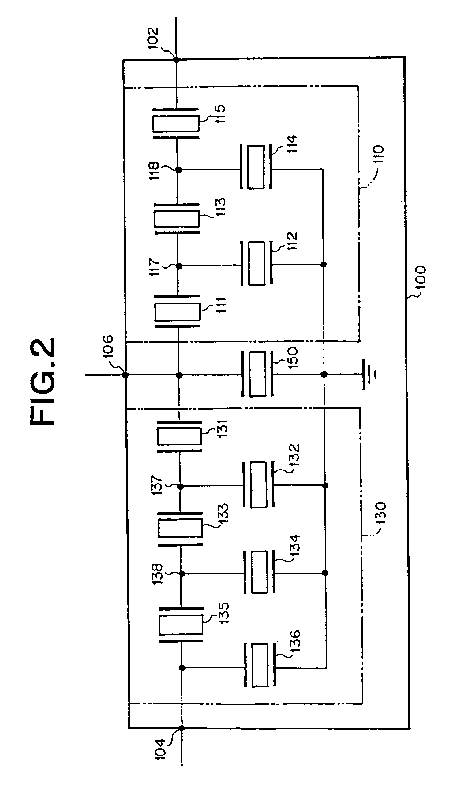
[0047]FIG. 1 is a block diagram showing a constitution of an embodiment of a duplexer or transmission / reception switch of the present invention. In FIG. 1, a duplexer 100 includes a transmission band filter 110, reception band filter 130, and film bulk acoustic resonator for adjustment 150. One end of the transmission band filter 110 is connected to a first port (transmission port) 102, and one end of the reception band filter 130 is connected to a second port (reception port) 104. The other ends of the transmission band filter 110 and reception band filter 130 are connected to a third port (antenna port which is a port both for transmission and reception) 106. For the film bulk acoustic resonator for adjustment 150, one end thereof is connected to the antenna port 106 (i.e., connected to the other ends of the transmission band filter 110 and reception band filter 130), and the ot...


PUM


Abstract

A transmission band filter (110) having a series of elements (111, 113, 115) each composed of a film bulk acoustic resonator and grounded shunt elements (112, 114) each composed of a film bulk acoustic resonator is connected between a transmission port (102) and an antenna port (106). A reception band filter (130) having a series of elements (131, 133, 135) each composed of a film bulk acoustic resonator and grounded shunt elements (132, 134, 136) each composed of a film bulk acoustic resonator is connected between a reception port (104) and the antenna port (106). A film bulk acoustic resonator (150) for adjustment is connected between the antenna port (106) and the ground. The resonance frequency of the adjusting film bulk acoustic resonator (150) lies between the upper limit frequency of the transmission frequency pass band of the transmission band filter (110) and the lower limit frequency of the reception frequency pass band of the reception band filter (130). Therefore a duplexer such that it can be a monolithic element, the power handling capability is good, the size is small, and the cost is low is provided.

Description

[0001]This application is a 371 of PCT / JP02 / 04575 filed on May 10, 2002, published on Nov. 21, 2002 under publication number WO 02 / 093763 A1 and claims priority benefits of Japanese Patent Application No. 2001-141847 filed May 11, 2001 and Japanese Patent Application No. 2001-375883 filed Dec. 10, 2001.TECHNICAL FIELD[0002]The present invention relates to a technical field of a communication apparatus, particularly to a filter and duplexer using a film bulk acoustic resonator.BACKGROUND ART[0003]There has constantly been a demand for miniaturization in an RF circuit portion of a cellular phone. In recent years, there has been a demand for various functions to be imparted to the cellular phone. To realize this, as many components as possible are preferably incorporated. On the other hand, since a size of the cellular phone is restricted, after all it is necessary to raise a mounting density in an apparatus. Therefore, a demand for reduction of an occupying area (mounting area) and he...

Claims


Application Information

Patent Timeline
Patent Type & Authority Patents(United States)
IPC IPC(8): H03H9/00H03H9/58H04B1/52H04B1/50H03H9/05H03H7/19H03H7/00
CPCH04B1/52H03H9/706H03H9/0571H03H7/19
Inventor NISHIMURA, KOSUKENAGAO, KEIGOHASHIMOTO, CHISENMASUI, EIJIKIMURA, HIROFUMI
Owner MEMS SOLUTIONS INC
Why Eureka
Try Eureka