Tire air pressure monitoring system

a technology of air pressure monitoring and tire position, which is applied in vehicle tyre testing, instruments, roads, etc., can solve the problems of troublesome operation, tire position association makes no sense, and the association between registered id codes and tire positions is not clear

Active Publication Date: 2005-04-26
DENSO CORP
View PDF7 Cites 69 Cited by
  • Summary
  • Abstract
  • Description
  • Claims
  • Application Information

AI Technical Summary

Benefits of technology

[0008]The present invention has been developed with a view to eliminating the above-mentioned problems, and it is therefore an object of the invention to provide a tire air pressure monitor

Problems solved by technology

However, the aforesaid registration of the ID code of each of the sensor units in the monitoring unit in a state associated with the tire position requires troublesome operations.
In addition, even in a case in which the ID code of each of the sensor units is registered in the monitoring

Method used


Image

  • Tire air pressure monitoring system
  • Tire air pressure monitoring system
  • Tire air pressure monitoring system

Examples


Embodiment Construction

[0027]An embodiment of the present invention will be described hereinbelow with reference to the drawings. This embodiment relates to an example in which a tire air pressure monitoring system according to the present invention is applied to a four-wheel passenger vehicle. However, the tire air pressure monitoring system according to the present invention is also applicable to other vehicles such as a motor truck and bus.

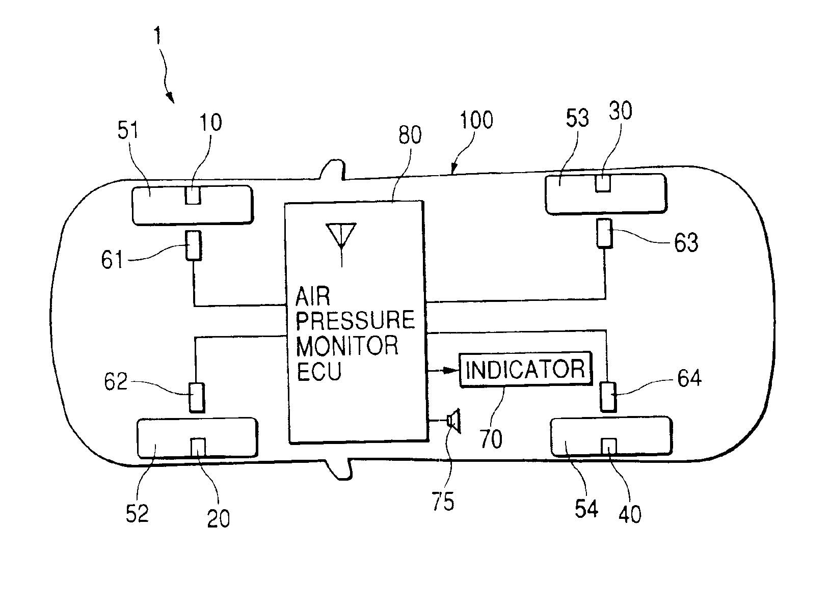
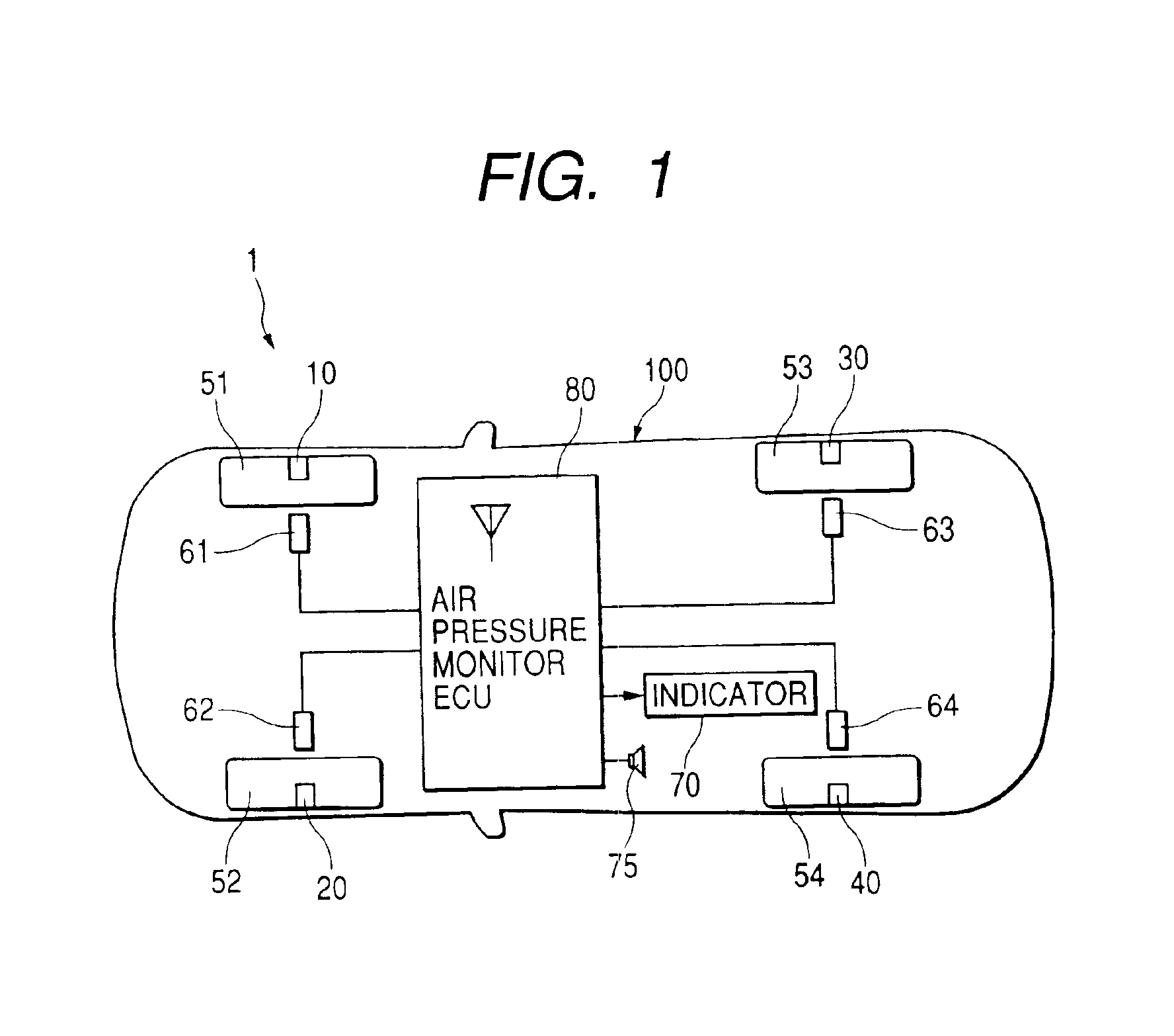
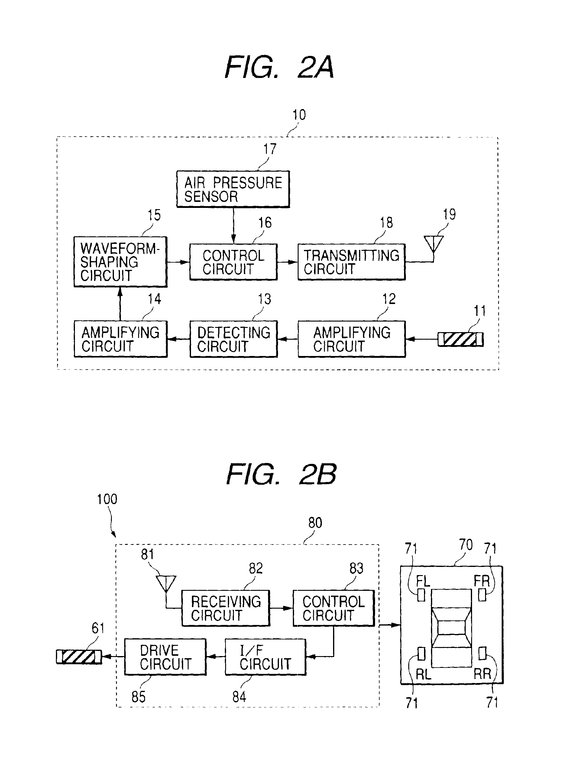
[0028]FIG. 1 is a schematic illustration of a configuration of a tire air pressure monitoring system according to this embodiment. As FIG. 1 shows, the tire air pressure monitoring system, generally designated at reference numeral 1, comprises sensor units 10, 20, 30 and 40 respectively provided in tires 51, 52, 53 and 54 of a vehicle for measuring tire air pressures and for transmitting signals including the air pressure measurement values. In addition, the tire air pressure monitoring system comprises a monitoring unit 100 provided in the vehicle side for receiving...


PUM


Abstract

Provided is a tire air pressure monitoring system capable of grasping the tire positions where there are sensor units even in the case of tire rotation. In the tire air pressure monitoring system, a trigger signal is transmitted from a transmission coil antenna to only the corresponding sensor unit in a manner such that a magnetic field is used as a medium and, upon receipt of the trigger signal, the sensor unit measures a tire air pressure and others and transmits a transmission signal including the measurement values to a monitoring unit. The monitoring unit makes a decision on the tire position where there is the sensor unit on the basis of the transmission signal from the sensor unit.

Description

BACKGROUND OF THE INVENTION[0001]1. Field of the Invention[0002]The present invention relates to a tire air pressure monitoring system designed to monitor an air pressure state of each of tires of a vehicle.[0003]2. Description of the Related Art[0004]So far, there have been proposed various types of systems for monitoring an air pressure of each of tires of a vehicle. One of such tire air pressure monitoring systems is disclosed in Japanese Patent No. 3212311 in which a sensor unit comprising a sensor for measuring a tire air pressure and a transmitter for transmitting the tire air pressure measurement value is provided in each of tires and a monitoring unit receives a signal transmitted from the sensor unit to address a warning if each tire air pressure measurement value falls below a predetermined value.[0005]In this conventional tire air pressure monitoring system, for grasping the position of the tire equipped with each of the sensor units, a specific ID code allocated to each ...

Claims


Application Information

Patent Timeline
IPC IPC(8): B60C23/04B60C23/02G01L17/00B60C19/00B60C23/00B60C23/20G08C17/02
CPCB60C23/0408B60C23/00
Inventor OKUMURA, RYOZO
Owner DENSO CORP
Why Eureka
Try Eureka