System, method, and computer program product for near-real time load balancing across multiple rendering pipelines

a computer graphics system and load balancing technology, applied in the field of computer graphics system performance, can solve the problems of not the rendering frame cannot proceed as quickly, and the performance of a multiple pipeline computer graphics system may not be much better than the performance of a single pipeline computer graphics system, so as to reduce increase the load of this pipeline, and increase processing.

Inactive Publication Date: 2005-04-26
MORGAN STANLEY +1
View PDF6 Cites 91 Cited by
  • Summary
  • Abstract
  • Description
  • Claims
  • Application Information

AI Technical Summary

Benefits of technology

[0012]At the completion of a frame, each rendering pipeline sends its performance report to a performance monitor. The performance monitor determines whether or not there was a significant disparity between the times required by the rendering pipelines to render their tiles. If a disparity is detected, and if the disparity is determined to be significant (i.e., greater than some threshold), then an allocation module resizes the tiles for the subsequent frame. If this is the case, the rendering pipeline bearing the largest processing load will have its tile reduced in size for purposes of the subsequent frame. This reduces the load of this pipeline. The rendering pipeline having the lowest processing load, as evidenced by its performance report, will then have its tile increased in size. The load on this pipeline is therefore increased. The latter pipeline will therefore have more processing to perform for purposes of the subsequent frame, while the former pipeline will have less rendering to perform. This serves to balance the load across rendering pipelines for the subsequent frame. This represents a near real time load balancing after each frame is rendered, allowing optimal use of the parallel architecture.

Problems solved by technology

If this is the case, then rendering the frame can only proceed as quickly as the slowest rendering pipeline.
While this example may be an extreme case, it shows that even given multiple rendering pipelines, in some situations the performance of a multiple pipeline computer graphics system may not be much better than the performance of a single pipeline computer graphics system.

Method used


Image

  • System, method, and computer program product for near-real time load balancing across multiple rendering pipelines
  • System, method, and computer program product for near-real time load balancing across multiple rendering pipelines
  • System, method, and computer program product for near-real time load balancing across multiple rendering pipelines

Examples


Embodiment Construction

I. Overview

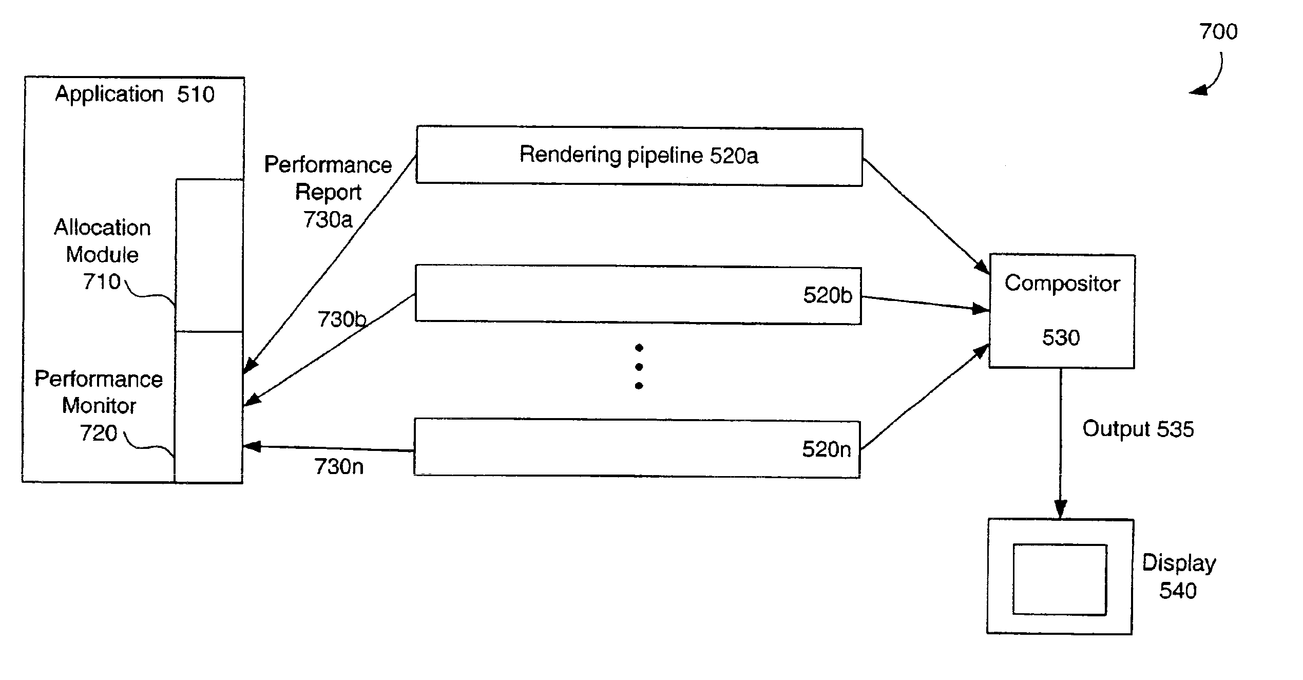
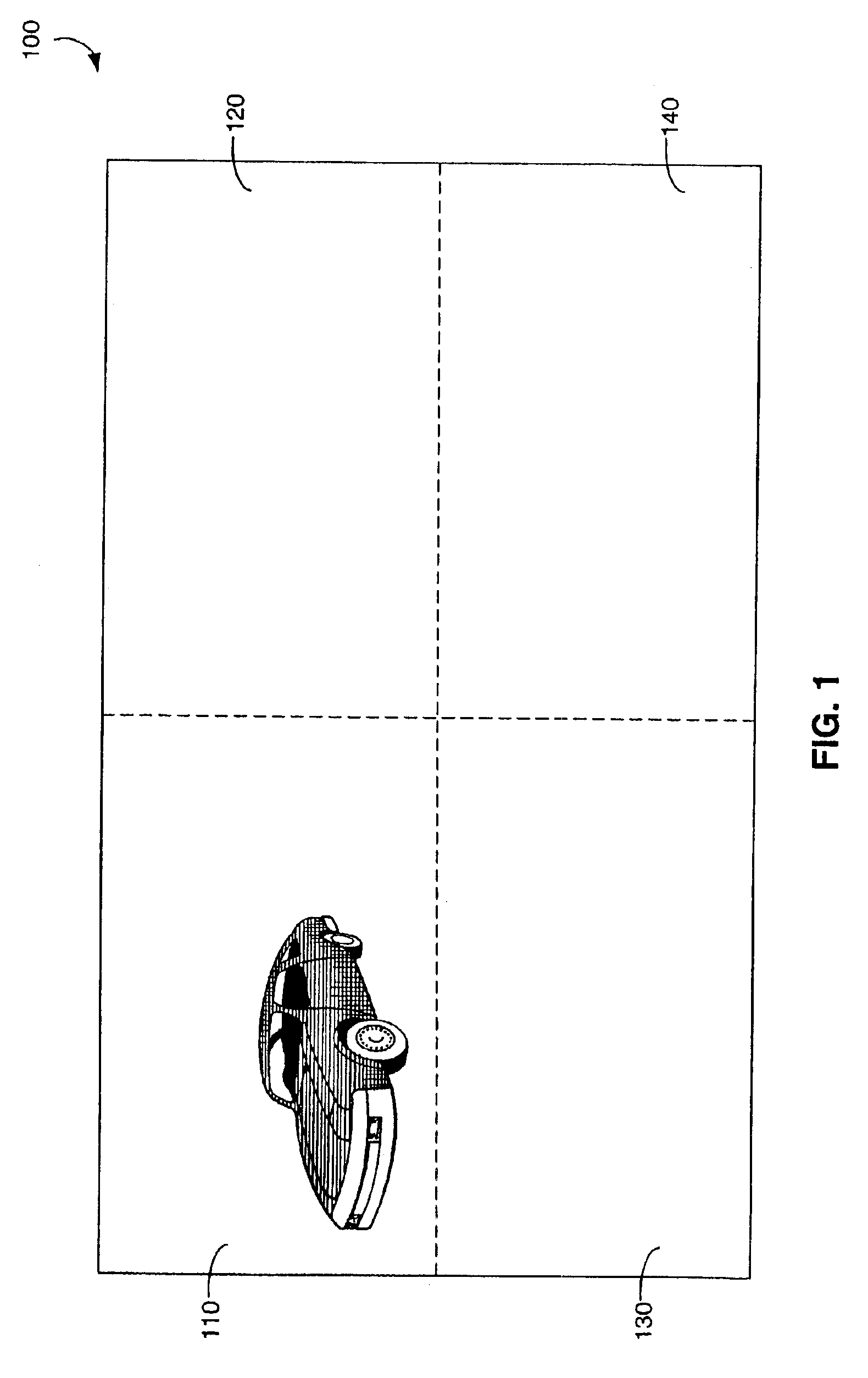
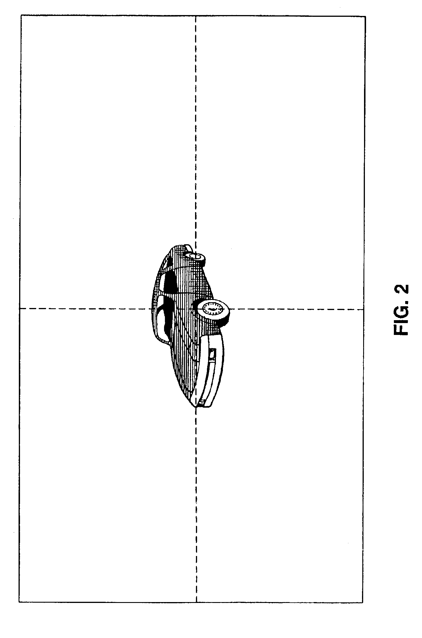
[0032]The invention described herein is a system, method, and computer program product for creating a sequence of computer graphics frames using a plurality of rendering pipelines. For each frame, each rendering pipeline renders a subset of the total amount of graphics data. The output of each rendering pipeline represents a portion of the frame. In an embodiment of the invention, each portion of the frame is rectangular. Each rectangle is referred to hereinafter as a tile. Each rendering pipeline is therefore responsible for the rendering of its own particular tile in a given frame. After completion of a frame, each rendering pipeline then produces a performance report. The performance report states the amount of time that was required to render a tile in the current frame. At the completion of a frame, each rendering pipeline sends its performance report to a performance monitor. The performance monitor determines whether or not there was a significant disparity between...


PUM


Abstract

A system, method, and computer program product for creating a sequence of computer graphics frames, using a plurality of rendering pipelines. For each frame, each rendering pipeline receives a subset of the total amount of graphics data for the particular frame. At the completion of a frame, each rendering pipeline sends a performance report to a performance monitor. The performance monitor determines whether or not there was a significant disparity in the time required by the respective rendering pipelines to render their tiles. If a disparity is detected, and if the disparity is determined to be greater than some threshold, an allocation module resizes the tiles for the next frame. This serves to balance the load across rendering pipelines for each frame.

Description

CROSS-REFERENCE TO RELATED APPLICATIONS[0001]Not applicable.STATEMENT REGARDING FEDERALLY-SPONSORED RESEARCH AND DEVELOPMENT[0002]Not applicable.[0003]REFERENCE TO MICROFICHE APPENDIX / SEQUENCE LISTING / TABLE / COMPUTER PROGRAM LISTING APPENDIX (submitted on a compact disc and an incorporation-by-reference of the material on the compact disc)[0004]Not applicable.BACKGROUND OF THE INVENTION[0005]1. Field of the Invention[0006]The invention described herein relates to computer graphics system performance.[0007]2. Background Art[0008]Computer graphics systems sometimes use parallelism in order to enhance performance. In particular, a graphics system may use more than one rendering pipeline in order to create an image. In such an architecture, each pipeline is responsible for rendering some portion of a frame. When rendering is completed, the outputs of the respective rendering pipelines are combined by a compositor to produce the complete frame. Such an arrangement can significantly increa...

Claims


Application Information

Patent Timeline
Patent Type & Authority Patents(United States)
IPC IPC(8): G06T15/00
CPCG06T15/005G06T2210/52
Inventor TANG-PETERSEN, SVENDKURZION, YAIR
Owner MORGAN STANLEY
Why Eureka
Try Eureka