Intelligent camera flash system

a camera flash and intelligent technology, applied in the field of intelligent camera flash system, can solve the problem of high cost of analysis of the output of each of these elements

Inactive Publication Date: 2005-04-26
FLASHPOINT TECH
View PDF7 Cites 24 Cited by
  • Summary
  • Abstract
  • Description
  • Claims
  • Application Information

AI Technical Summary

Benefits of technology

[0011]It is another object of the present invention to provide an improved digital camera having a flash system providing a series of lower power flashes prior to a final flash utilizing a single capacitor and providing for optimum use of flash energy.
[0018]An advantage of the present invention is the provision of a flash system for a digital camera that provides optimum flash energy.
[0019]A further advantage of the present invention is that it provides a flash system that uses reduced energy flashes in the determination of exposure, thus conserving total flash energy.
[0020]Another advantage of the present invention is the provision of a flash system that conserves flash energy and operates from a single flash capacitor.
[0021]A further advantage of the present invention is the use of the image acquisition optics to determine exposure, thus providing increased accuracy and a reduced parts cost.
[0022]It is a further advantage of the present invention to provide a flash system that determines exposure based on center weight sampling, giving greater importance in exposure determination to a more important area of the image.

Problems solved by technology

In either the case of ambient or flash light sources, the above described scaling is not performed if the degree of exposure is extremely under exposed (low clipping) or extremely over exposed (high clipping), since a meaningful histogram cannot then be prepared.
An analysis of the output of each of these elements would be a very expensive project, and for this reason the pixels are sampled (block 71).

Method used


Image

  • Intelligent camera flash system
  • Intelligent camera flash system
  • Intelligent camera flash system

Examples


Embodiment Construction

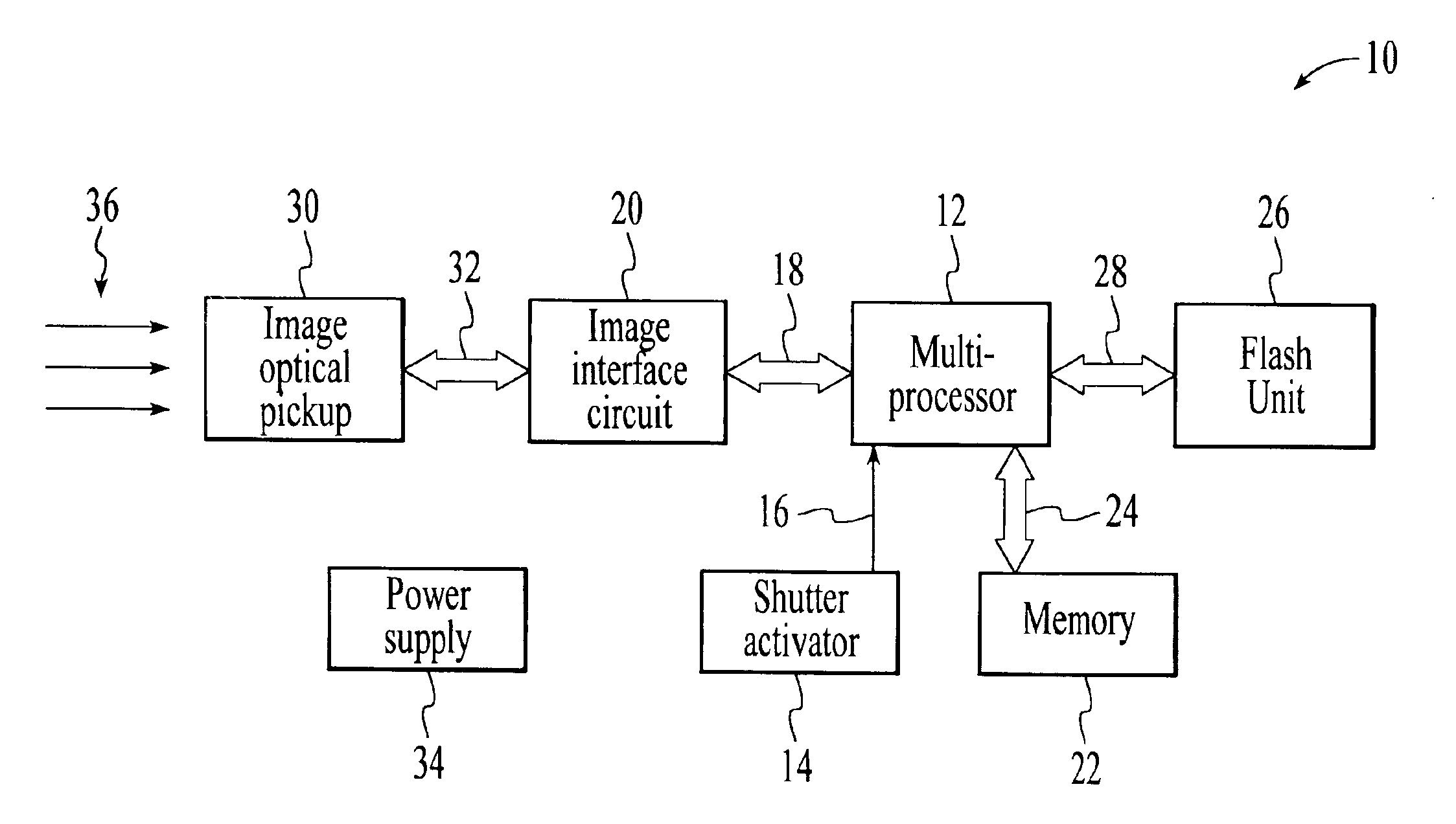
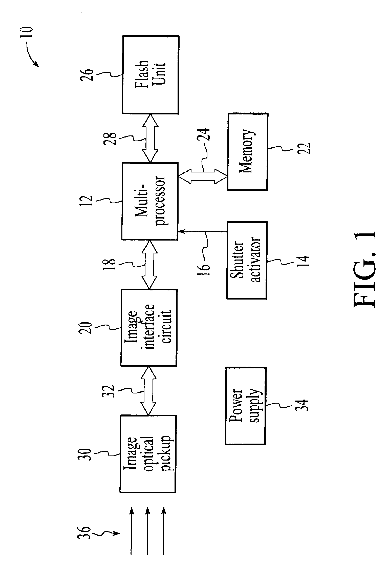
[0037]A typical camera system in which the method and apparatus of the present invention is employed is shown in FIG. 1, wherein a digital camera 10 is illustrated having a multiprocessor 12 activated by shutter activator 14 through line 16, and communicating through bus 18 with image interface circuit 20. The multiprocessor further communicates with memory 22 through bus 24 and interconnects with the flash unit 26 through bus 28. Image optical pick-up 30 is interconnected to the image interface circuit 20 through bus 32. A power supply 34 is shown for providing electrical energy to the various circuit components through lines not shown.

[0038]In response to the shutter activator 14, light 36 from an image to be recorded is received by the image optical pick-up 30 and sent via bus 32 to the image interface circuit 20 which communicates with the pick-up 30 and processor 12 to provide digital image intensity data corresponding to the light 36. Further details of the pick-up 30 and circ...


PUM


Abstract

An intelligent flash system for a digital camera having components including an image optical pickup, an interface circuit, a flash unit and a processor. Upon activation of the camera, ambient lighting conditions are evaluated and if flash energy is required, a first low energy pre-flash is radiated, the reflected light received by the optical pickup having a multiplicity of pixels, and the output of the pixels converted to image intensity data by the interface circuit. The processor samples the image intensity data, weighing the center image area more heavily, and creates a histogram plot of quantity of pixels v.s. intensity, and separates the plot into a bar graph from which a determination of exposure is obtained. The histogram is then used to calculate a multiplicative scaling factor used to multiply the first flash energy to an estimate of a flash energy for correct exposure. Conditions of extreme over and under exposure result in the activation of a second flash at an adjusted energy level. The image data of the second flash is then analyzed and the exposure compared with the result of the first flash. A final determination of flash energy is then made based upon the results.

Description

[0001]This application is a continuation of Ser. No. 08 / 624,972 filed Mar. 28, 1996, now U.S. Pat. No. 6,151,073.BACKGROUND OF THE INVENTION[0002]1. Field of the Invention[0003]The present invention relates generally to electronic digital cameras, and more particularly to a digital camera using a pre-flash in combination with digital camera image acquisition apparatus and a processor for creating a histogram to determine an optimum flash power controlled through calculation of flash capacitor voltage.[0004]2. Brief Description of the Prior Art[0005]Prior art cameras have used many different techniques to achieve optimum exposure, from hand held light meters to built in automatic exposure systems with flash. One method of controlling exposure is based on “through the lens” flash control in which the flash is terminated when sufficient light is collected by a photo receptor in the camera. Another method uses an infrared photo diode to measure the light. The advantage of using infrared...

Claims


Application Information

Patent Timeline
Patent Type & Authority Patents(United States)
IPC IPC(8): G03B7/16H04N5/235
CPCH04N5/2354G03B7/16H04N23/74
Inventor STEINBERG, ERANVASUDEV, HARIMEHRA, SUMAT
Owner FLASHPOINT TECH
Why Eureka
Try Eureka