Transmission/reflection type color liquid crystal display device

a liquid crystal display device and reflection display technology, applied in non-linear optics, instruments, optics, etc., can solve the problems of significant reduction in color purity, significant reduction in brightness in reflection display mode, and inability to achieve color reproducibility

Inactive Publication Date: 2005-04-26
SHARP KK
View PDF12 Cites 56 Cited by
  • Summary
  • Abstract
  • Description
  • Claims
  • Application Information

AI Technical Summary

Benefits of technology

[0020]In a reflection display mode where ambient light is used, light entering the liquid crystal display device from the front side (viewer side) passes through the color filter or the color filter openings, is reflected by the reflection regions of the reflection film, and passes again through the color filter or the color filter openings to the outside, whereby combined output light of non-colored output light and colored output light is obtained, thus realizing a bright display. The brightness and saturation of the output light can be adjusted by adjusting, as necessary, the characteristics of the color filter and the area and shape of the color filter openings. By enlarging the color filter openings, a color filter having a high color purity can be employed.
[0021]In the liquid crystal display device of the present invention, it is preferred that the color filter includes a plurality of openings in the reflection region. In this way, non-colored output light is output to the first substrate side while being dispersed across each pixel in a reflection display mode, whereby bright regions are dispersed across each pixel, thus improving the visibility.
[0022]In the liquid crystal display device of the present invention, it is preferred that the reflection film is a diffused reflection film whose surface on the liquid crystal layer side has irregularities. In this way, in a reflection display mode, reflected light from the reflection film passes through the color filter to the first substrate side while being diffused, whereby the brightness and the saturation of the combined output light are made uniform across each pixel, thus improving the visibility.
[0023]In the liquid crystal display device of the present invention, it is preferred that an area proportion of the transmission region with respect to the pixel region is equal to or greater than 10% and less than or equal to 50%, and an area proportion of the opening with respect to the reflection region is equal to or greater than 5% and less than or equal to 30%. In this way, it is possible to realize a transflective color liquid crystal display device that is satisfactory for practical use in a reflection display mode and in a transmission display mode. Specifically, a sufficient brightness can be ensured in a transmission display mode by setting the area proportion of the region where the reflection film is not formed (i.e., the transmission region) to be 10% or more, and a sufficient brightness can be ensured in a reflection display mode by setting it to be 50% or less. On the other hand, a sufficient brightness can be ensured in a reflection display mode by setting the color filter opening proportion to be 5% or more, and a sufficient color area can be ensured in a reflection display mode, whereby different colors can be distinguished from one another, by setting it to be 30% or less. In order to perform an evaluation in a reflection display mode, the color filter opening proportion is herein represented in relation to the area of the reflection region. This is because the size of the opening of the color filter significantly influences a reflection display.
[0025]In the liquid crystal display device of the present invention, it is preferred that the openings of the color filter are filled with a transparent resin whose transmittance is 90% or more. In this way, the step around each color filter opening is eliminated, whereby the liquid crystal molecules rise in a uniform manner in the vicinity of each color filter opening, thus improving the contrast (particularly the contrast in a reflection mode). A flattening film made of an acrylic resin is layered on the surface of the color filer for flattening the surface irregularities of the color filter. Thus, when the color filter openings are shallow, the openings are filled with the flattening film. However, when the color filter openings are deep, unless the openings are filled with a transparent resin, the step around each opening cannot be eliminated by the flattening film, thus leaving a step. Particularly when an STN liquid crystal material is used, the liquid crystal molecules rise in a non-uniform manner in each pixel due to the presence of such a step around each color filter opening, thereby causing significant problems such as a reduction in the contrast in a reflection display mode.
[0034]With such a liquid crystal display device, if a transparent plastic substrate present in the path along which light from a light source such as a backlight travels gets yellowish through a production process, the area proportion of the color filter of blue, which is approximately the complementary color to yellow, can be increased relative to those of the red and green color filters. Therefore, in a transmission display mode, the transmitted light can be approximately white light in a white display, thereby realizing a transmission color display with a desirable color reproducibility.

Problems solved by technology

Moreover, if a color filter with a high saturation (low transmittance) is employed in an attempt to increase the display color saturation in a transmission display mode, the brightness in a reflection display mode decreases considerably, thereby lowering the visibility significantly.
Moreover, reflected light from the reflection film on the inner surface of the back-side substrate and reflected light from the transflective reflector on the reverse surface of the back-side substrate are both used, thereby causing problems such as a decrease in the color purity due to the parallax caused by the presence of the back-side substrate.
However, when a transflective color liquid crystal display device is produced by using a plastic substrate instead of using a glass substrate as in the prior art, a colorless and transparent plastic substrate gets yellowish in some cases through a production process such as heating during a color filter deposition, a transparent electrode film deposition or an alignment film deposition.
In such a case, the color displayed image as a whole gets yellowish not only in a reflection display mode but also in a transmission display mode, thereby causing a decrease in the color reproducibility.

Method used


Image

  • Transmission/reflection type color liquid crystal display device
  • Transmission/reflection type color liquid crystal display device
  • Transmission/reflection type color liquid crystal display device

Examples


embodiment 1

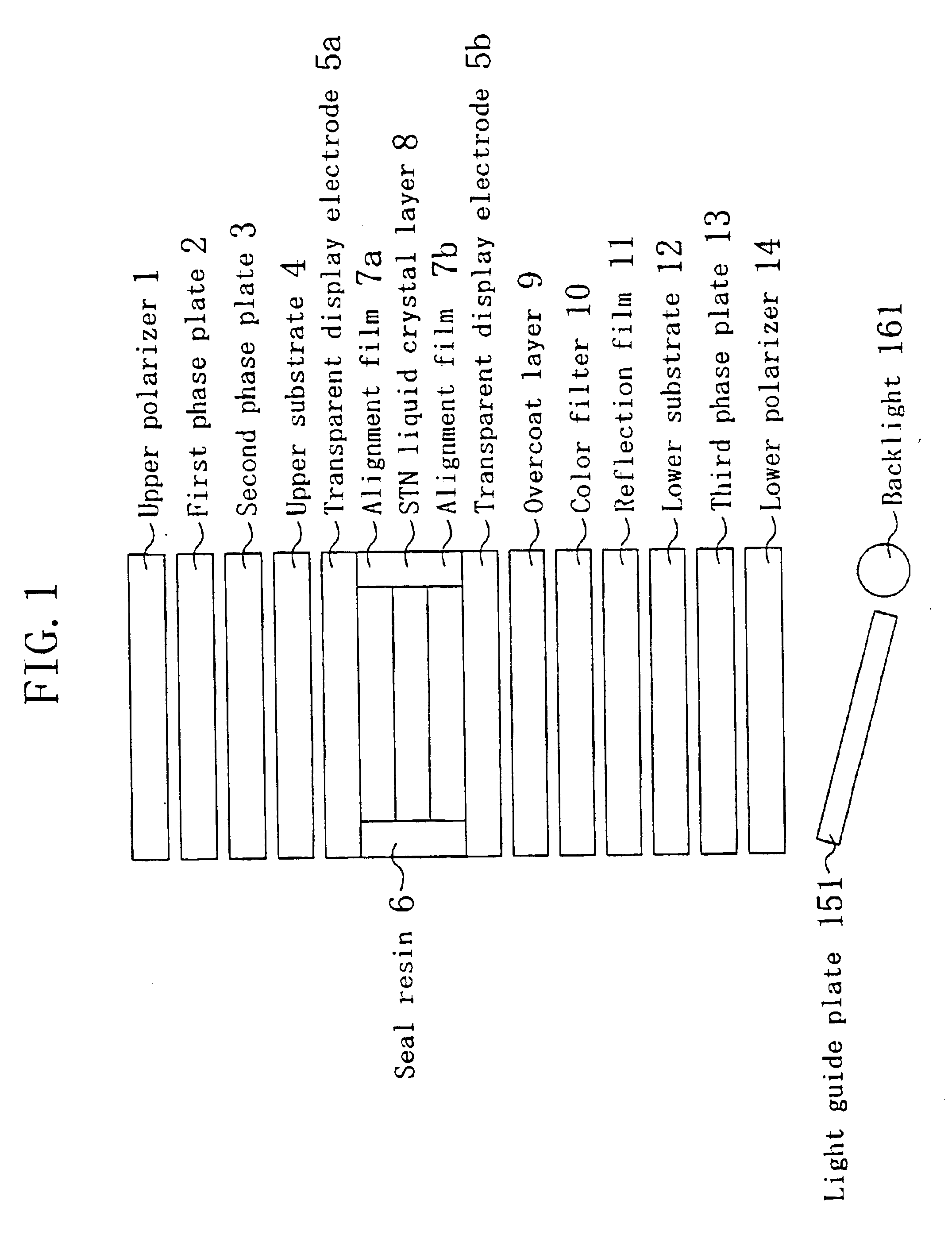
[0059]FIG. 1 is a diagram schematically illustrating a transflective color liquid crystal display device of the present embodiment. The transflective color liquid crystal display device of the present embodiment includes an upper polarizer 1, a first phase plate 2, a second phase plate 3, an upper substrate 4, a transparent display electrode 5a, an alignment film 7a, an STN liquid crystal layer 8, an alignment film 7b, a transparent display electrode 5b, an overcoat layer 9, a color filter 10, a reflection film 11, a lower substrate 12, a third phase plate 13, a lower polarizer 14, a light guide plate 151 and a backlight 161. These components are layered in this order from the viewer side (the upper side in FIG. 1). The upper substrate4 and the lower substrate 12 are attached to each other via a seal resin 6 therebetween, thereby forming the STN liquid crystal layer 8.

[0060]The liquid crystal display device of the present embodiment includes a plurality of pixel regions arranged in ...

embodiment 2

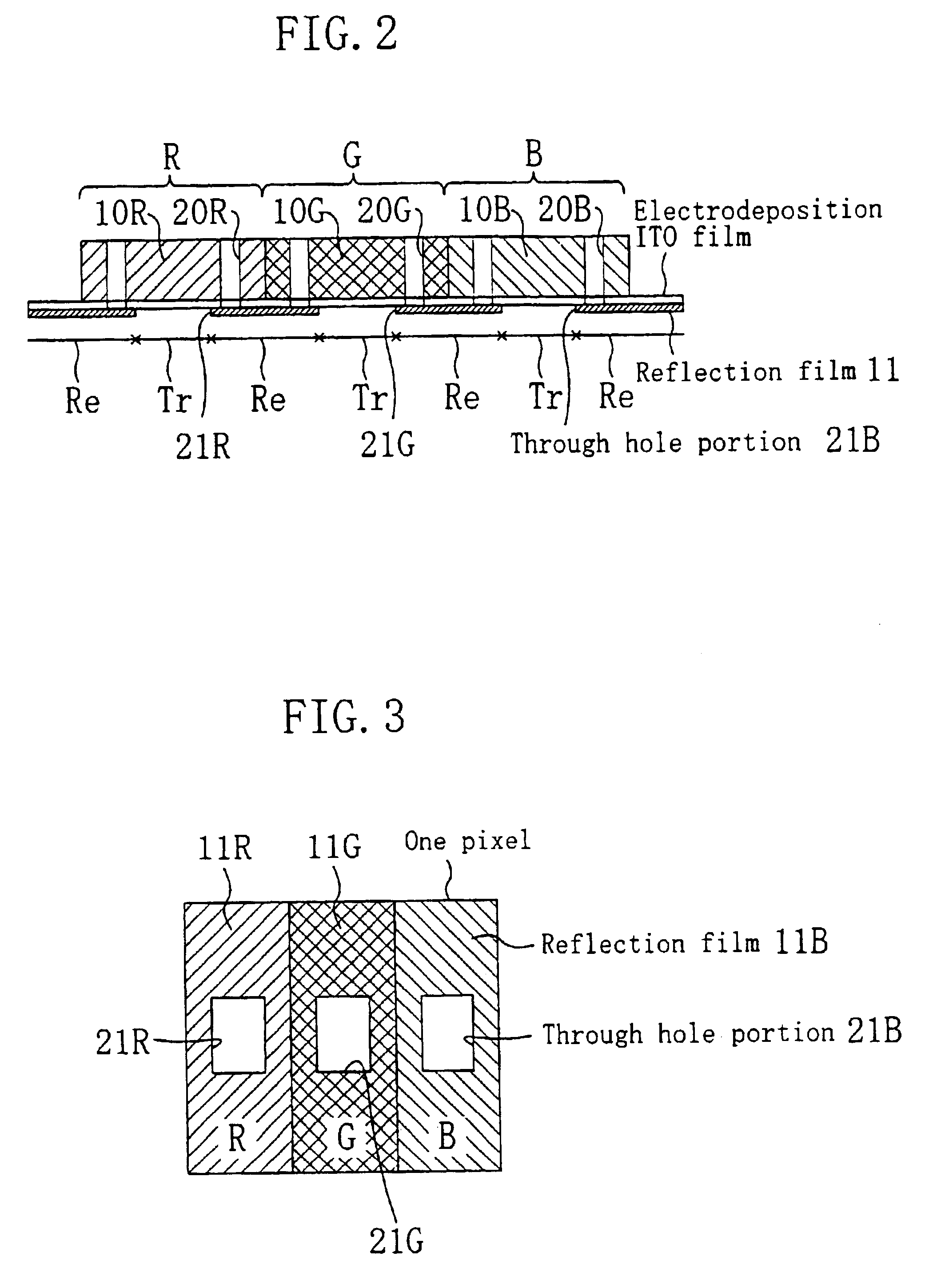
[0099]FIG. 13 is a plan view schematically illustrating one pixel of the liquid crystal display device of Embodiment 2, and FIG. 14 is a cross-sectional view illustrating the same taken along line x-x′. In the present embodiment, three pixels of different hues (R, G and B) together form a picture element. The R, G and B color filters 10R, 10G and 10B include a number of respective openings 20R, 20G and 20B within a pixel region. In the present embodiment, the color filters 10R, 10G and 10B include two rectangular openings 20R, 20G and 20B, respectively, in each pixel region.

[0100]In the present embodiment, the color filter 10B in a blue pixel region has openings the size (area) of which is smaller than those of the color filters 10R and 10G in red and green pixel regions. Therefore, the blue color filter 10B, among the R, G and B color filters 10R, 10G and 10B, has the largest color filter area for coloring the reflected light from the reflection film 11.

[0101]Moreover, in the prese...

embodiment 3

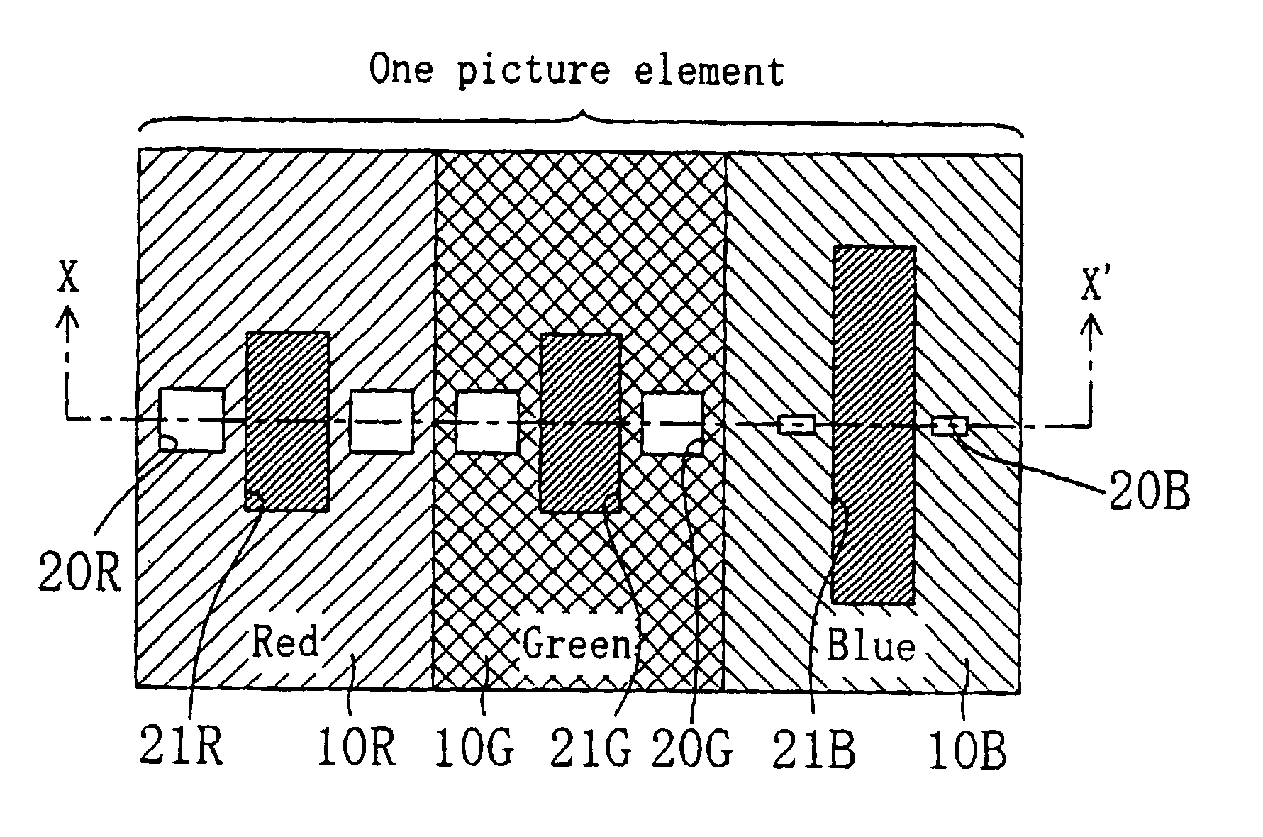
[0114]FIG. 16 is a plan view schematically illustrating one picture element in a transflective color liquid crystal display device of Embodiment 3. The color liquid crystal display device of the present embodiment is different from that of Embodiment 2 in that the openings 21R, 21G and 21B of the reflection film 11 in the R, G and B pixel regions have an equal size (area) among the R, G and B pixels.

[0115]In the color liquid crystal display device of the present embodiment, the size (area) of the opening 20B of the color filter 10B in the blue pixel region is smaller than those of the openings 20R and 20G of the color filters 10R and 10G in the red and green pixel regions. Therefore, the blue color filter 10B, among the R, G and B color filters 10R, 10G and 10B, has the largest color filter area for coloring the reflected light from the reflection film 11.

[0116]With the color liquid crystal display device of the present embodiment, if the upper plastic substrate 4 gets yellowish thr...


PUM

PropertyMeasurementUnit
transmittanceaaaaaaaaaa
reflectanceaaaaaaaaaa

Abstract

A liquid crystal display device, including: a first substrate; a second substrate; opposing the first substrate; a liquid crystal layer interposed between the first substrate and the second substrate; a reflection film formed on one side of the second substrate that is closer to the liquid crystal layer; and a color filter formed on the reflection film, wherein: a plurality of pixel regions are arranged in a matrix pattern, each of the pixel regions including a reflection region where light coming from the first substrate side is reflected by the reflection film back to the first substrate side, and a transmission region where light coming from the second substrate side is transmitted to the first substrate side; and the color filter includes an opening in the reflection region.

Description

[0001]This application is a continuation of application Ser. No. 10 / 092,421, filed Mar. 7, 2002, now U.S. Pat. No. 6,501,521.BACKGROUND OF THE INVENTION[0002]1. Field of the Invention[0003]The present invention relates to a transmission / reflection type (hereinafter “transflective”) color liquid crystal display device having both reflection and transmission functions. A transflective color liquid crystal display device operates in a reflection display mode using ambient light from around the device under bright environments and in a transmission display mode using light from the backlight under dark environments. The liquid crystal display device of the present invention is suitable for use in various applications, including OA equipment such as word processors and personal computers, personal digital assistants such as electronic organizers, and camcorders with a liquid crystal monitor.[0004]2. Description of the Background Art[0005]A transflective color liquid crystal display devic...

Claims


Application Information

Patent Timeline
Patent Type & Authority Patents(United States)
IPC IPC(8): G02F1/1335G02F1/13
CPCG02F1/133555
Inventor MATSUSHITA, TOMOHISAYOSHIMURA, KAZUYASAKUWA, TOHRU
Owner SHARP KK
Why Eureka
Try Eureka