
Synchronization in digital data transmission systems

Inactive Publication Date: 2005-04-26
NEC CORP
View PDF9 Cites 34 Cited by
  • Summary
  • Abstract
  • Description
  • Claims
  • Application Information

AI Technical Summary

Benefits of technology

[0013]It is an object of the present invention to provide a channel estimation method which is capable of performing a channel estimation with successfully even on a fading channel.

Problems solved by technology

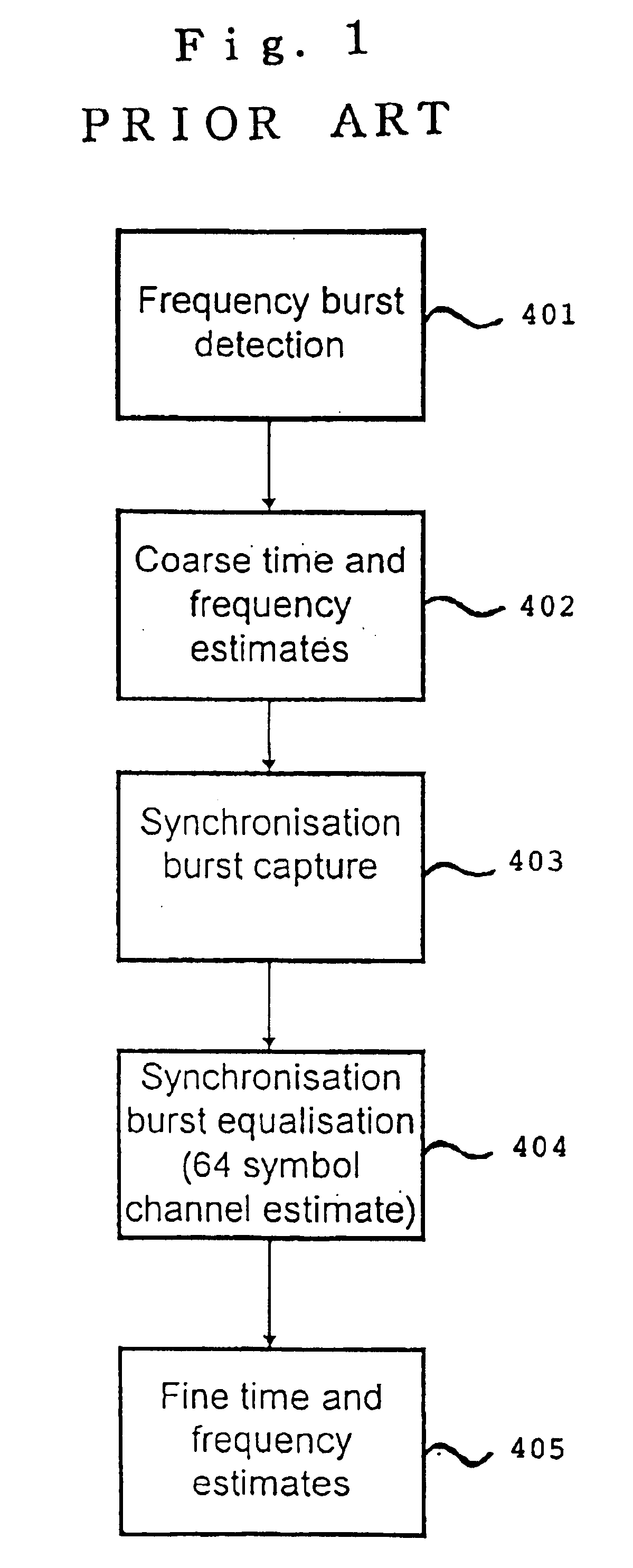
The current arrangements for Synchronization Burst equalization are limited in performance by their intolerance to residual frequency offsets arising from the estimate of the frequency derived from the Frequency Burst.
Under these conditions the mobile terminal is likely to fail to synchronize with the network.
This is typically not the case, however, on a real fading channel when the mobile terminal is trying to gain initial synchronization with the network.
When the bit error rate for the equalized burst exceeds that which can successfully be tolerated by the channel coding used to protect the information contained in the SB, then the synchronization will fail.

Method used


Image

  • Synchronization in digital data transmission systems
  • Synchronization in digital data transmission systems
  • Synchronization in digital data transmission systems

Examples


Embodiment Construction

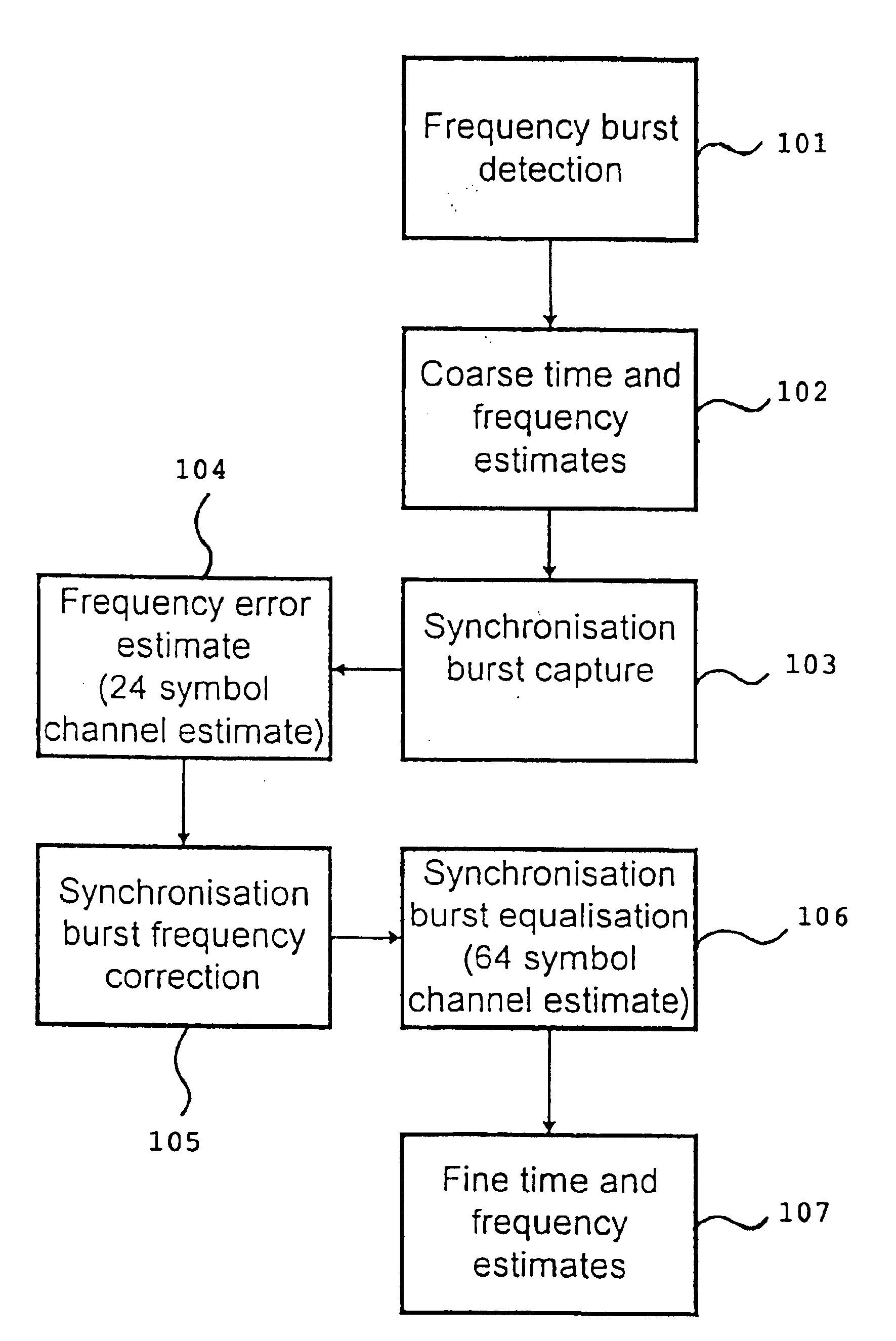
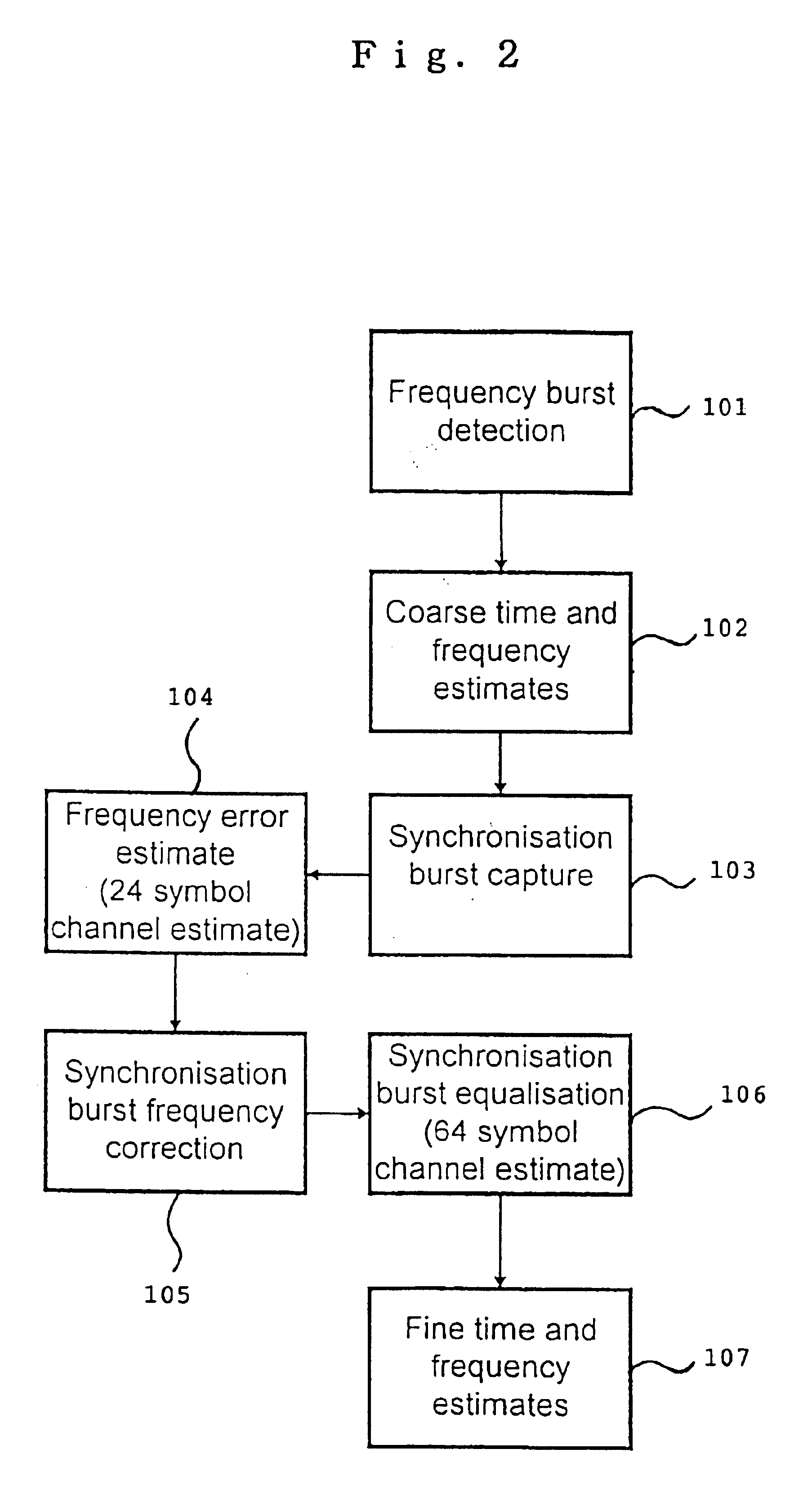
[0020]A means for an improvement over the prior art methods in the tolerance to residual frequency error of the Synchronization Burst decoding process is illustrated in the flow diagram of FIG. 2. The frequency burst detection (step 101) and coarse time and frequency estimates (step 102) are obtained in the usual manner in accordance with prior art methods.

[0021]A GSM training sequence is shown in FIG. 3 with each of the symbols labelled 1 to 64. It is convenient here to show the training sequence as comprising three sections labelled A, B and C. The full sequence of symbols from 1 to 64 is transmitted consecutively, however, and FIG. 3 serves to illustrate as section B the 24 symbol sub set used to obtain the frequency error estimate. The symbols 1 through 64 would be the training sequence expected to be received by the mobile phone terminal.

[0022]Returning to FIG. 2, at capture of the synchronization burst (step 103) the received training sequence is cross correlated with the subs...


PUM


Abstract

A channel estimation method for a digital telecommunication station is disclosed. A frequency correction burst is sought by scanning of the wanted channel. The frequency correction burst is used to provide coarse time and frequency synchronizations. A synchronization burst is received. Calculating the cross-correlation of the expected training sequence with the training sequence contained in said synchronous burst to obtain a channel estimate. A frequency error estimate is derived from the channel estimate, and the frequency error of the received burst is corrected in accordance with said frequency error estimate. The received synchronous burst is equalized. The frequency corrected symbols are used to refine the time and frequency synchronizations.

Description

BACKGROUND OF THE INVENTION[0001]1. Field of the Invention[0002]The present invention relates to digital data transmission, and more particularly to digital data decoders.[0003]2. Description of the Related Art[0004]Reference is made to U.S. Pat. Nos. 5,838,672 to Ranta and 5,479,444 to Malkamaki et al and “Mobile Radio Communications” published by John Wiley & Sons, Raymond Steele (Ed.) for a description of the prior art and technological background.[0005]The following description is based on the GSM cellular communications system for which the invention is of particular utility. It will be apparent to those skilled in the art, however, that the invention may be applied to other systems of digital data transmission.[0006]When a mobile phone terminal is to be used to communicate via a network, it must first obtain synchronization with the network. This is essentially a three step passive process. The mobile terminal must synchronize with the base station transmission in time, then f...

Claims


Application Information

Patent Timeline
IPC IPC(8): H04B7/26H04L7/04H04L27/00H04B7/005H04L7/00
CPCH04B7/2675H04L7/042H04W56/0085H04W56/0035H04L2027/0095H04L2027/0065
Inventor BURTON, MARK
Owner NEC CORP
Learn More